Triton FT5000 PC-BASED ATM Installation Manual User Manual
Page 33
33
E
XTENDED
C
ONFIGURATION
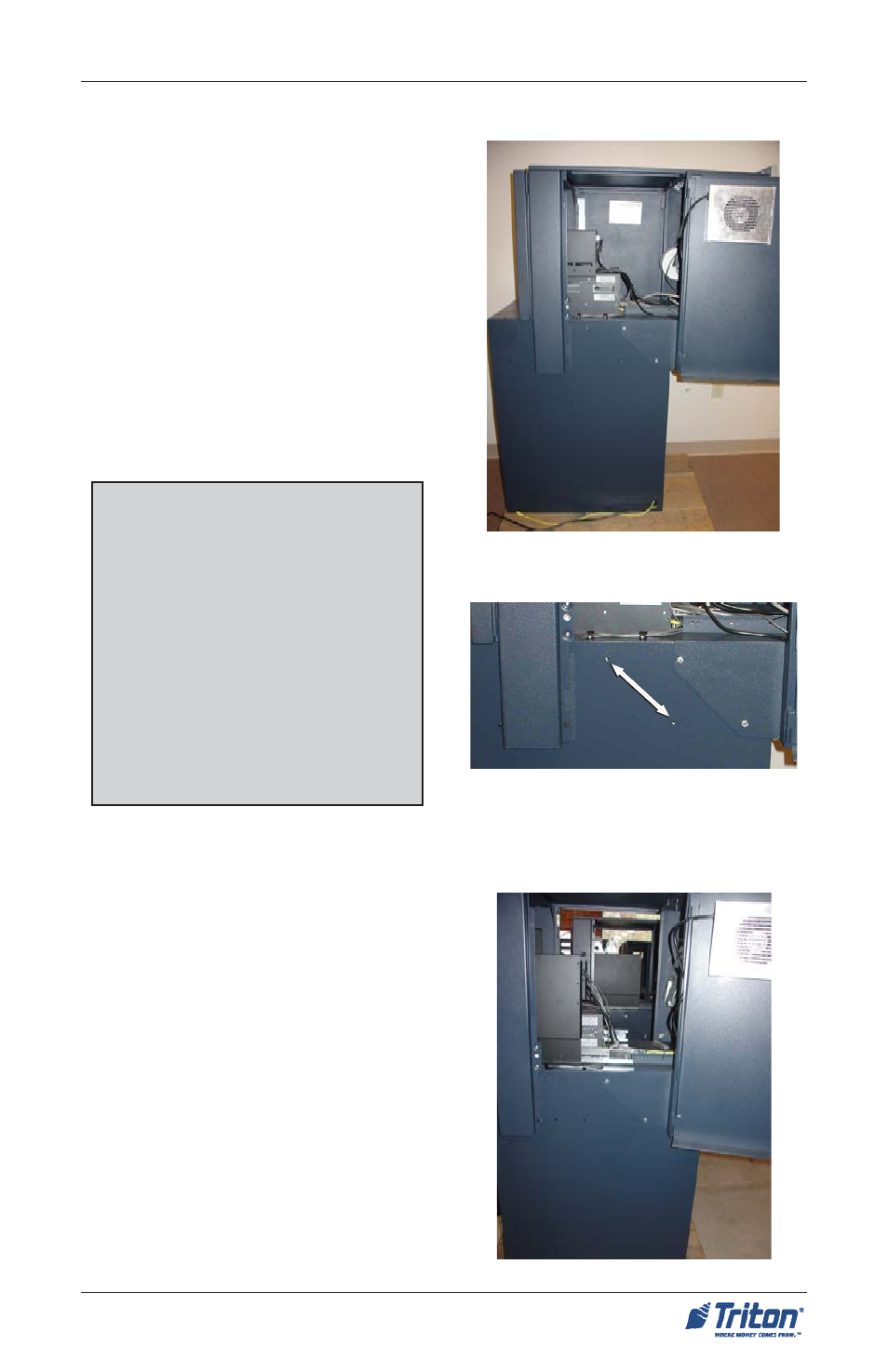
The illustration on right shows the
FT5000
XP
extended. The primary pur-
pose for this configuration is for instal-
lation in facilities with exterior walls hav-
ing a maximum thickness of 10 inches
(254 mm). The dispensing mechanism
has a bill chute extension designed for
the elongated configuration. A protec-
tive plate is inserted on the underside
of the cabinet sleeve for security and
environmental purpose.
The illustration on right shows the
FT5000
XP
“collapsed” or Island con-
figuration. The cabinet sleeve is moved
back approximately 5 - 7/16" inches (137
mm). This configuration allows instal-
lation in facilities with exterior walls hav-
ing a maximum thickness of 6 - 1/4"
inches (160 mm). The dispensing mecha-
nism has a shortened bill chute exten-
sion due to the collapsed state of the
unit.
I
SLAND
C
ONFIGURATION
**Warning**
Units are shipped as specified con-
figurations and the dispensing mecha-
nism assembled with the required bill
chute extension. Changing configu-
rations require dispenser modifica-
tions and/or additional hardware.
YOU CAN NOT CHANGE
CABINETCONFIGURATIONS
WITHOUT THE REQUIRED
HARDWARE.
S
ITE
P
REPARATION
/I
NSTALLATION
Figure 12. Extended co nfiguration.
Figure 14. Island con figuration.
Figure 13. Screw holes for
Island configuration.