Ft5000 – Triton FT5000 PC-BASED ATM Installation Manual User Manual
Page 46
46
FT5000
XP
- S
ITE
P
REPARATION AND
I
NSTALLATION
G
UIDE
2. Pick up the dispensing mecha-
nism by the handles and load it
on to the slide rail by aligning the
tabs (under handle) into the rail
slots. (Figures 1 and 2)
I
NSTALLING THE
D
ISPENSING
M
ECHA
-
NISM INTO THE
C
ABINET
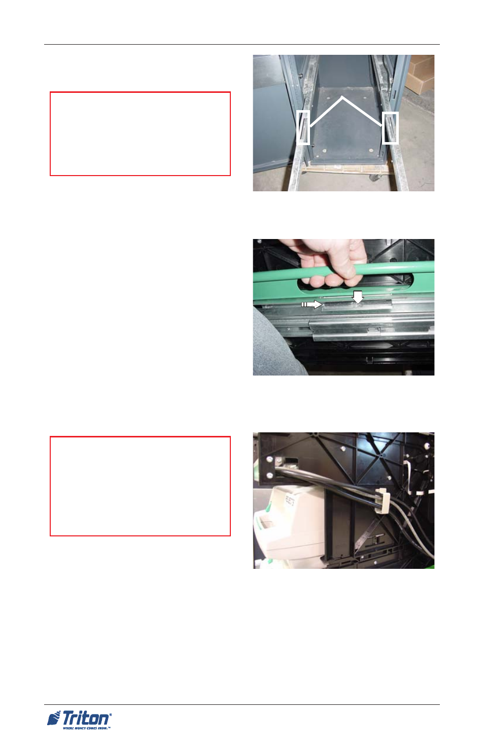
1. Refer to Figure 1. Pull the slide
rails out of the cabinet until they
reach their fully extended posi-
tion. The left slide rail has a lock-
ing pin that must be disengaged
to extend the rail. Ensure all cables
have been moved out of the way
so they will not be damaged while
installing the dispensing mecha-
nism in the cabinet.
Rail slots
Figure 2. T ab into rail slot. Use 2-
person lift!
Tab
Rail slot
**CAUTION**
Be certain that you have not applied
power to the ATM before you con-
tinue! See Pg.44 for the ATMs power
supply location and On/Off switch.
Figure 1. Slide rails extended.
***WARNING***
Use only the green handles and
drive motor in rear of dispenser to
lift the mechanism. Two persons
recommended to install the dis-
penser on to the slide rails.
3. Refer to Figure 3. Route the dis-
pensers AC power, shutter, and se-
rial data cables as shown in Figure
3 (right side of dispenser).
Figure 3. Route cables through cable
clip.