Ft5000 – Triton FT5000 PC-BASED ATM Installation Manual User Manual
Page 32
32
FT5000
XP
- S
ITE
P
REPARATION AND
I
NSTALLATION
G
UIDE
Speaker wires
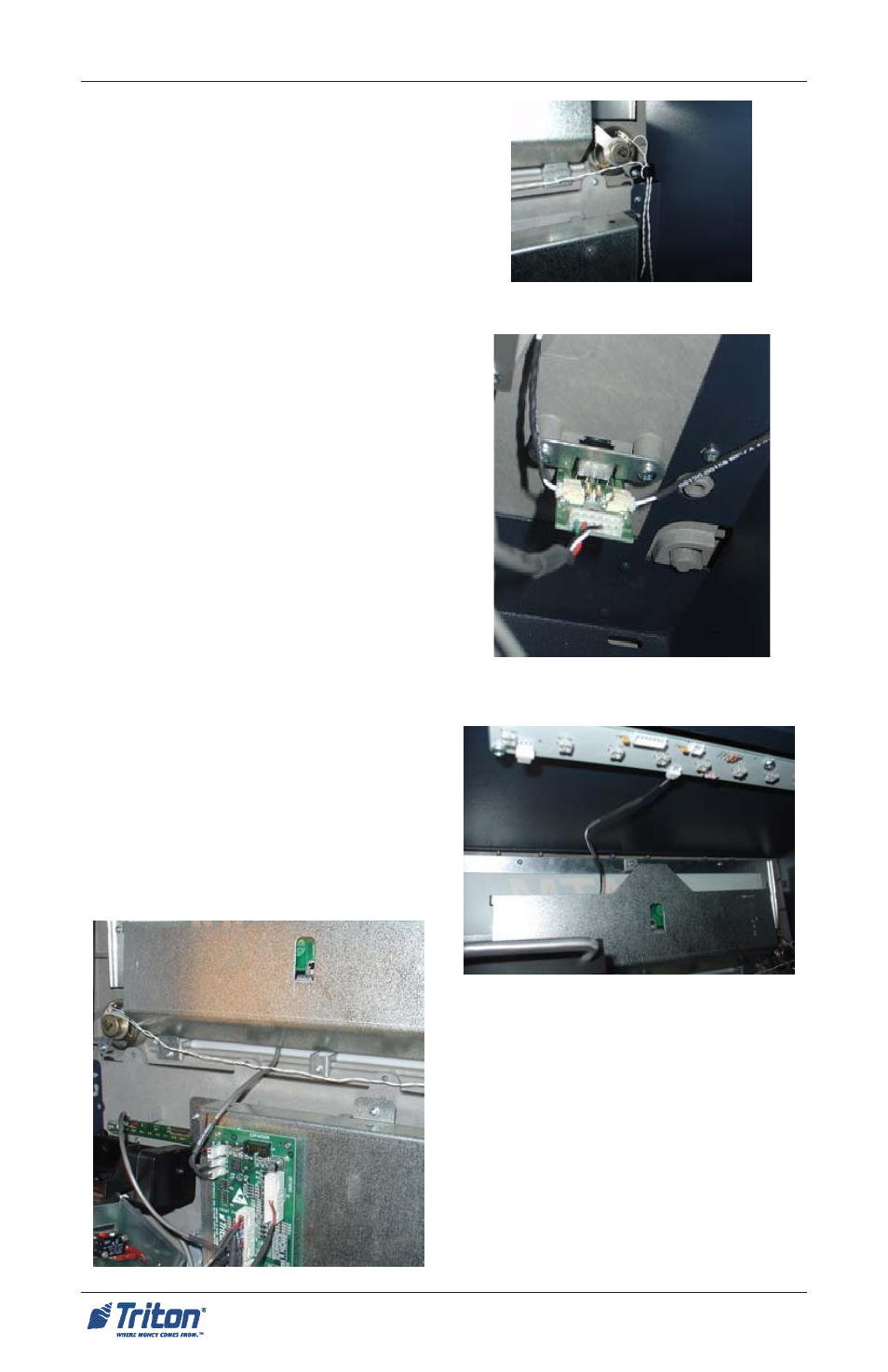
4. After the control panel trim has
been secured, route the speaker
wires through the cable clip shown
in Figure 3. Connect the speaker
wires to the audio input circuit
board located in the lower right
corner of the cabinet (Figure 4).
5. Connect the trims upper LED light
cable to the cabinets LED light
assembly shown in Figure 5.
Connect the lower cable to the
docking board assembly (J3)
shown in Figure 6.
6. With 2 persons (inside/outside),
slide the whole unit back inside
until the control panel trim is flush
with the outside wall.
7. Before securing/anchoring the
cabinet, check to ensure the control
panel trim is flush against the
exterior wall. Minor adjustments
can be made using the cabinet
leveling feet.
8. Secure/anchor the cabinet to the
floor or plinth, if used. Cabinet/trim
installation is complete.
Figure 3. Route speaker wires.
Figure 5. Upper trim cable con-
nected to LED light assembly.
Figure 6 (Left). Lower cable
connected to docking board (J3).
Figure 4. Connect speaker wires to
audio board.
- X-SCALE/X2 Configuration Manual (419 pages)
- ARGO Installation Manual (35 pages)
- ARGO User Manual (97 pages)
- ARGO G60 Installation Manual (31 pages)
- ARGO Quick Reference Guide (10 pages)
- RL331X TRAVERSE User Manual (74 pages)
- FT5000 X2 User Manual (105 pages)
- FT5000 X2 Quick Reference Guide (10 pages)
- 81XX/91XX (including X2)/97XX/RL16XX (5 pages)
- RL1600 Installation Manual (41 pages)
- RL1600 Quick Reference Guide (7 pages)
- RL1600 User Manual (72 pages)
- RL2000 POWER CORD Installation Manual (1 page)
- RL2000 User Manual (124 pages)
- RL2000 Installation Manual (45 pages)
- RL2000 Quick Reference Guide (10 pages)
- RL5000 X2 Series User Manual (122 pages)
- RL5000 X2 Series Installation Manual (55 pages)
- RL5000 X2 Series Quick Reference Guide (12 pages)
- 8100/9100/97XX/RL5000 (X-SCALE/XP) (10 pages)
- 8100 Quick Reference Guide (6 pages)
- 8100 User/Installation Manual (150 pages)
- 9100 Installation Manual (50 pages)
- 9100 Quick Reference Guide (8 pages)
- 9100 User Manual (172 pages)
- 9100 Electronic Lock Installation Manual (8 pages)
- 96XX CASH DISPENSER CABINET Installation Manual (6 pages)
- 9650 Operation Manual (264 pages)
- 9600 Series Quick Reference Guide (2 pages)
- 9640 Operation Manual (265 pages)
- 9600 Operation Manual (209 pages)
- 9610 Series Quick Reference Guide (2 pages)
- 9610 Operation Manual (210 pages)
- 97XX Series Operation Manual (265 pages)
- 9710 Series Quick Reference Guide (2 pages)
- 9700 Series Quick Reference Guide (2 pages)
- 9705 Series Quick Reference Guide (2 pages)
- 9200 Installation Manual (26 pages)
- 9200 Operation Manual (179 pages)
- MAKO 2000 Operation Manual (217 pages)
- MAKO PEDESTAL Installation Manual (8 pages)
- MAKO EXTENDED CABINET Installation Manual (7 pages)
- RT2000 X2 User Manual (109 pages)
- RT2000 X2 Installation Manual (36 pages)
- RT2000 X2 Quick Reference Guide (8 pages)