Nmd-100 d, Ft5000, Nmd-100 – Triton FT5000 PC-BASED ATM Installation Manual User Manual
Page 44
44
R
EMOVING
/I
NSTALLING THE
NMD-100 D
ISPENSING
M
ECHANISM
The dispensing mechanism for the
FT5000
XP
unit is shipped mounted on
the slide rails inside the security
vault. Several protective foam packs
have been strategically placed behind
and along each side of the dispensing
mechanism to reduce any movement
during transit. The foam packs and
cardboard that secures the cassettes
must be removed before the dispens-
ing mechanism can be extended out.
Follow the procedures below for re-
moval.
FT5000
XP
- S
ITE
P
REPARATION AND
I
NSTALLATION
G
UIDE
R
EMOVING
T
HE
NMD-100
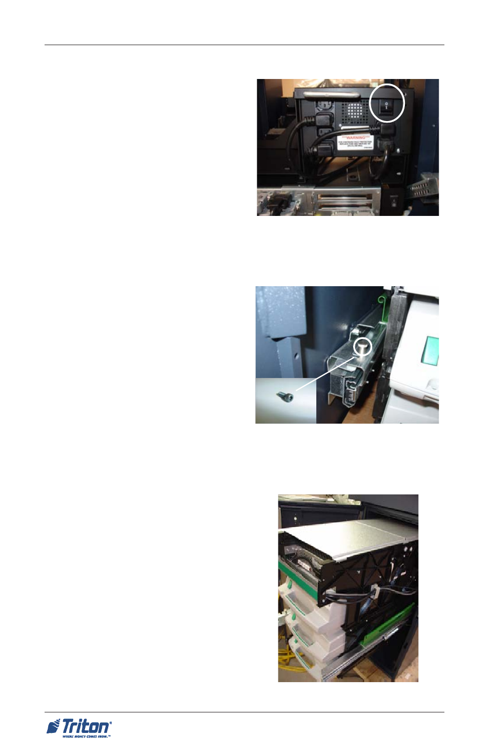
1. Unlock and open the control
panel sleeve door. Verify that the
power switch located on the
power supply (Figure 1) is in the
OFF (0) position. Close the
control panel door.
Figure 1. Ensure power supply is in
the OFF (0) position.
2. Open the security vault and re-
move all protective foam packs
from around the dispensing
mechanism.
3. Remove the transport 5/32" Allen
screws located on top front of
both slide rails (Figure 2). DIS-
CARD SCREWS AFTER RE-
MOVAL!
Figure 2. Remove and discard
transport screw, if applicable.
4. Pull the dispensing mechanism
out of the cabinet until it reaches
its fully extended position (Fig-
ure 3). The left slide rail has a
locking pin that must be disen-
gaged to extend the rail (Figure
2).
Locking pin
Locking pin
Allen screw
Figure 3. Dispenser fully extended.