Triton FT5000 PC-BASED ATM Installation Manual User Manual
Page 29
29
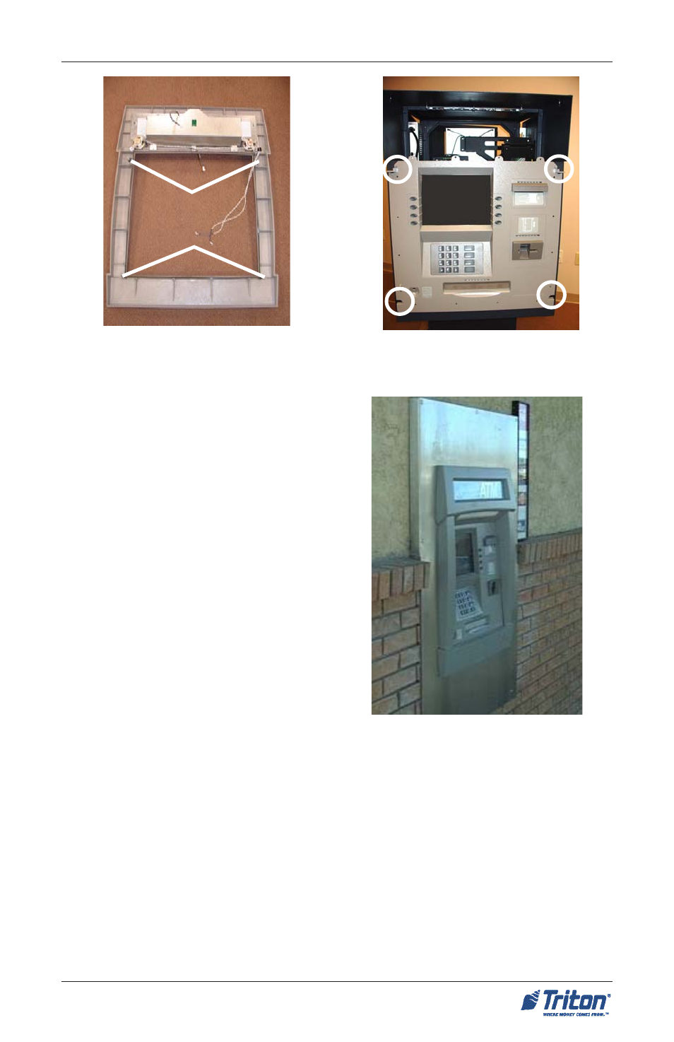
10. Slide the unit back until the control
panel trim is flush to the exterior
wall (Figure 7).
9. Temporarily mount the trim on the
protruding sleeve. DO NOT secure
with screws at this time.
S
ITE
P
REPARATION
/I
NSTALLATION
Figure 7. Slide unit back flush to wall.
Figure 6a. Location of clips on con-
trol panel trim.
Figure 6b. Location of slots on sleeve
control panel.
11. Adjust the plinth’s leveling feet to
ensure the control panel trim is flush
against the exterior wall and the
cabinet is level.
12. Mark the anchor holes through the
cabinet floor or mark around the
plinth structure using masking
tape, pencil, etc. Remove the
control panel trim and slide the unit
back inside.
13. Remove the unit from the plinth (if used). Align the plinth over the markings and
mark the anchor holes. Drill the anchor holes and secure the plinth (if used) to
the floor. Mount the unit back on the plinth (if used) and again slide the unit
forward towards the wall opening until the sleeve protrudes slightly out the
front exterior.
If no plinth was used, after drilling the anchor holes, again slide the unit forward
towards the wall opening until the sleeve protrudes slightly out the front exterior
.
Page 31 continues with the installation of the control panel trim.