Fig. 16, 4 manual 21:1 gearbox ratio option – Hired-Hand RollSeal Rollup Curtains: ROLLUP CURTAIN SYSTEM Rev 11-05 User Manual
Page 24
Part No. 4801-5138 Rev 11-05
Rollup Curtain System
Page 24
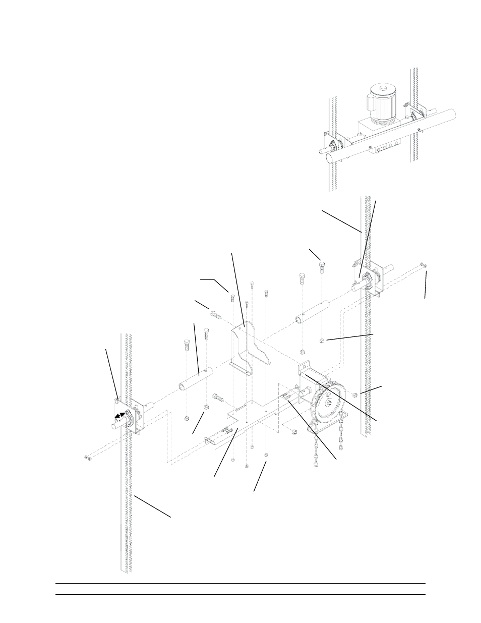
9.4 Manual 21:1 Gearbox Ratio Option
1. Install right pinion assembly (6419-0100) to rack (1059-6004) as shown in Fig.
16. Run pinion assembly about half way down rack as shown.
2. Repeat for left pinion assembly (6419-0104) and rack (1059-6004). NOTE:
Make sure that both pinion assemblies are the same distance from top of racks.
3. Attach gear pinion sleeve (0404-1457) to the pinion assembly (6419-0100).
4. Repeat for second pinion assembly. Use 3/8x16x2 HEX screws (1004-1423)
and 3/8x16 lock nuts (1001-1457) to attach pinion adapters to pinion assembly.
5. Install the Upright Mounting Bracket(0404-6790) to the Gear Bracket(0404-
6789) with four 1/4x20x11/2 screws (1004-7075) and 1/4x20 Lock Nuts
(1001-1457) provided.
6. Install Rollup drive assembly to each end of motor/gear box. Fasten gear
pinion sleeves (1001-1457) to each end of motor shaft with 3/8x16x1 screws
(1004-1426) & nuts (1001-1457) provided.
7. Attach the Rollup Drive Gear Bracket (0404-6789) to the motor with 3/8x16x1
hex screws (1001-1426).
8. Attach the Rollup Drive Gear Bracket (0404-6789) to the bottoms
of the pinion assemblies with 1/4x20x11/2 HEX screws (1001-
7075) and nuts (1001-1446) provided.
9. Go to Section 13 to attach the
Rollup Drive Rack Mounts
(0404-5141) to the top and
bottom of the racks.
Rack
1001-1446
Lock Nut 1/4x20
1004-7074
Screw 1/4x20
1004-1423
Screw 3/8x16x2
1001-1457
Lock Nut 3/8x16
0404-6789
Gear Bracket
1001-1446
Lock Nut 1/4x20
0404-6790
Upright Mounting
Bracket
3017-7070
Gear Box
Assembly
1001-1426
Screw 3/8x16x1
1001-1457
Lock Nut 3/8x16
0404-5647
Pinion Sleeve
1001-1457
Lock Nut 3/8x16
6419-0104 Rollup
Pinion
Assembly-Left
6419-0100
Rollup Pinion
Assembly-Right
Rack
1004-7075
Screw
1/4x20x11/2
Fig. 16
6450-5444 Manual
Drive 21:1
Assembled
4' - 6450-5423
5'.- 6450-5422
10' - 6450-8017