Hired-Hand Light Traps: Installing Light Trap for Fan User Manual
Installing light trap for fan, S warning, Description
Hired-Hand Mfg., Inc. • 1733 Co Rd 68 • Bremen, Alabama 35033 • Phone 256-287-1000 • Fax 256-287-2000
Sheet Part No. 4801-5500 Rev. 12-05
Page 1 of 4
Description
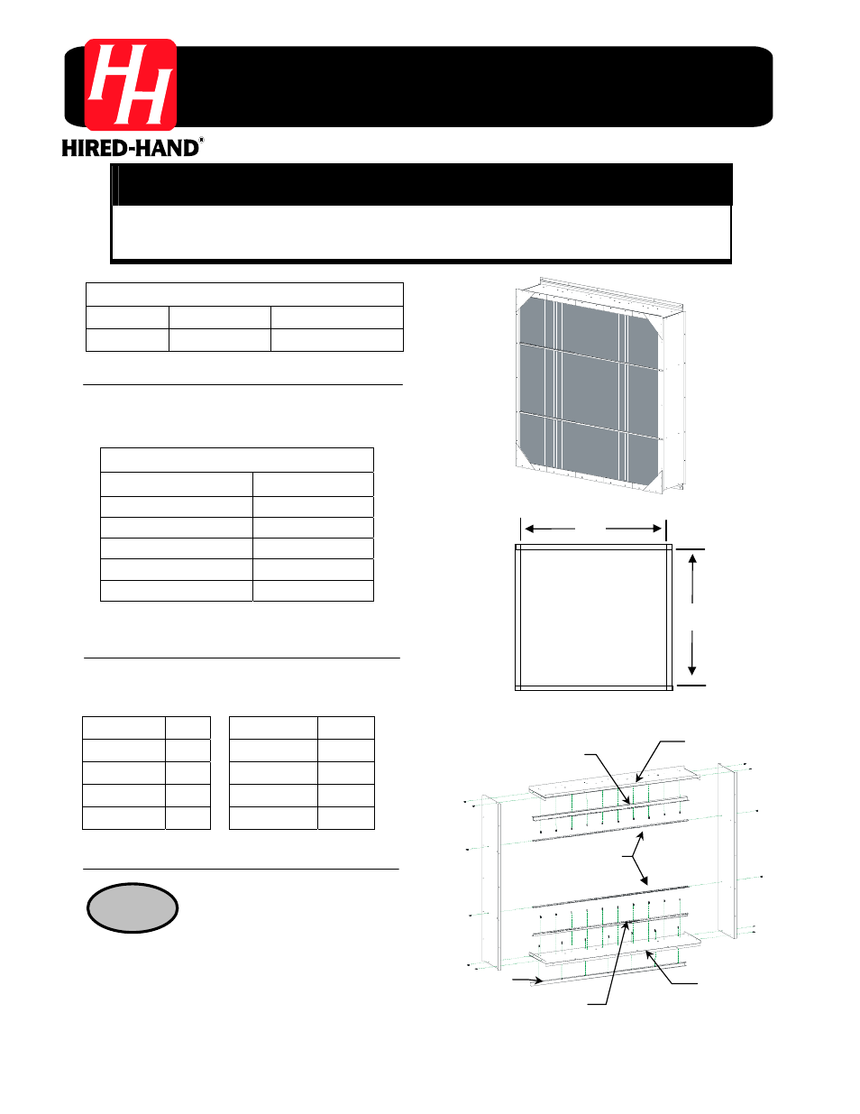
These instructions are for a Light Trap installed over a fan used
in a poultry confinement building. See Figure 1. The Light trap
is available in sizes shown in Table 1.
Framing Dimensions
The framing dimensions for the Light Traps are shown in
the following table. See Figure 2 for framing layout.
Assembly Instructions
Installing Light Trap for Fan
S Warning!
Disconnect All Electrical Power Sources Before Installing Light Trap
!
Locate a flat surface on the
ground and assemble the Top, Bottom
and Sides using 3/8" x ½" tap screws
(1004-0080). See Figure 3.
STEP 1
Figure 1 – Light Trap over Fan
Tools Required
Power Drill
Level
Tape Measure
3/8
"
Driver
5/16
"
Driver
1/4
"
Driver
Figure 3 – Assemble Top, Bottom and Sides
Flange to top
Bottom Support Channel
Flange to bottom
Top Extrusion Spacer
Back Extrusion
Spacer
Bottom Extrusion Spacer
H
W
Figure 2 – Light Trap Framing Dimensions
Table 1 - Light Trap Models
Light Trap Size
Part Number
72"(H)x72"(W) Blackout
6624-2100
72"(H)x60"(W) Blackout
6624-2101
60"(H)x60"(W) Blackout
6624-2102
48"(H)x48"(W) Blackout
6624-2103
36"(H)x36"(W) Blackout
6624-2099
Trap Width
W
Trap Height
H
72" 72"
72" 72"
60" 60"
60" 60"
48" 48"
48" 48"
36" 36"
36" 36"