Hired-Hand Baffles, Vents, & Inlets: Installing Ceiling Inlets User Manual
Installing ceiling inlets, Warning, Description
Part No. 4801-0180 Rev 11-08
Installing Ceiling Inlets
Page 1 of 2
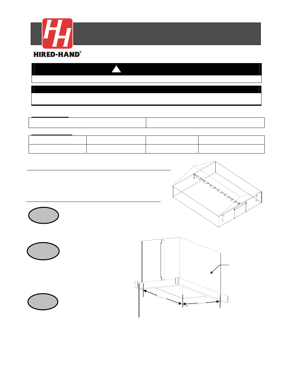
Figure 2 – Ceiling Inlet Framing Diagrams
STEP 3
Figure 1 – Ceiling Inlet
A
B
WARNING
Disconnect all Electrical Power before installing the Ceiling Inlet
Part Numbers
Part Number 6609-2100 / Model 2000 CFM SS Series 201
Part Number 6609-2101 / Model 4000 CFM SS Series 201
Tools Required
Drill
Flat Head Screwdriver
Socket set
5/16" Driver Bit
Drill Bit -1/4" dia.
Pliers 7/16"
wrench
Description
These instructions are for a Double Door Ceiling Inlet. See Figure 1 and
Figure 5.
Double Door Installation Instructions
Installing Ceiling Inlets
!
IMPORTANT!
Locate packing slip and make sure that all listed parts are enclosed. If not, call your Hired-Hand distributor
immediately. Please read and understand all instructions in this manual before installing Ceiling Inlets.
Frame in the opening 26 ¼” x 26 ¼“
for the Model 2000 or 46 1/2” x 20 3/4” for the
Model 4000. See Figure 2.
STEP 1
STEP 2
Staple the insulation stop to
the framed opening flush with the bottom
side of the trusses. The ends of the
insulation stop on double units will overlap
with lock tabs as shown in Figure 2.
Attach the inlet to the framed
opening using flat head screws (1015-1386).
The doors may be removed for this step.
Insulation Stop
Model 2000 A=26 1/4" B=26 1/4"
Model 4000 A=46 1/2" B=20 3/4"