Network interfaces, Serial management interface (console port), Reset button – Brocade FastIron GS and GS-STK Hardware Installation Guide User Manual
Page 17: Draft: brocade confidential, Figure 7, Figure 8, Hardware features
Brocade FastIron GS and GS-STK Hardware Installation Guide
7
53-1002186-02
Hardware features
1
DRAFT: BROCADE CONFIDENTIAL
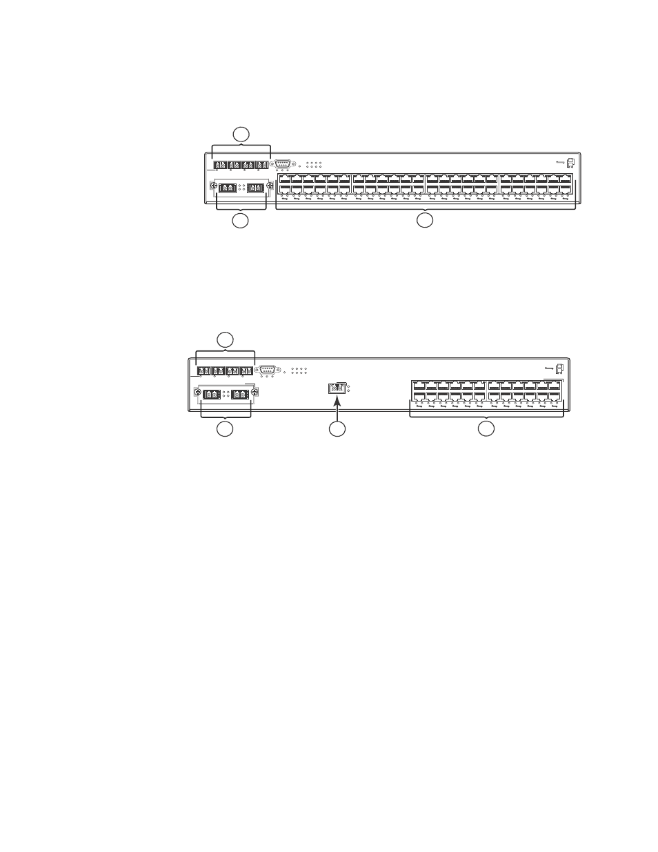
FIGURE 7
FGS648P-STK and FGS648P-POE-STK Front Panel
FIGURE 8
FGS624XGP and FGS624XGP-POE Front Panel
Serial management interface (Console port)
The serial management interface (the port labelled Console) enables you to configure and manage
the device using a third-party terminal emulation application on a directly-connected PC. A
straight-through EIA/TIA DB-9 serial cable (M or F) ships with the device. The console port is located
in the left corner of the front panel.
Reset button
The reset button allows you to restart the system without switching the power supplies off and on,
or using the CLI or Web management interface. The button is located to the right of the console
port and is recessed to prevent it from being pushed accidentally.
Network interfaces
describes the network interfaces supported on the FGS and FGS-STK devices. For network
interface specifications, refer to
1
Gigabit fiber ports 1F-4F
2
Optional 2-port 10 Gigabit Ethernet module, ports 49 and 50
3
Gigabit Ethernet copper ports 1-48
1
Gigabit fiber ports (slot 1, ports 1F-4F)
2
Optional 2-port 10 Gbps module (slot 2, ports 1 and 2
3
1-port 10 Gbps module (slot 3, port 1)
4
Gigabit copper ports (slot 1, ports 1-24)
49
1F
2F
3F
4F
Console
50
Lnk
Act
PS1 PS2 Pwr
5 6 7 8
1
1
2
2 3
Stack
4
3
4
5
6
7
8
9
10
11
12
13
14
15
16
17
18
19
20
21
22
23
24
25
26
27
28
29
30
31
32
33
34
35
36
37
38
39
40
41
42
43
44
45
46
47
48
Odd
Even
PoE
Lnk-Act
Lnk
Act
1
2
3
1F
2F
3F
4F
Console
Lnk
Act
PS1 PS2 Pwr
5 6 7 8
1
1
2
2 3
Stack
4
3
4
5
6
7
8
9
10
11
12
13
14
15
16
17
18
19
20
21
22
23
24
Odd
Even
PoE
Lnk-Act
Lnk
FGS-2XG
Act
Lnk
Act
Slot 2
1
2
Slot 3
Slot 1
1
2
4
3