Table 8, Figure 18 – Brocade VDX 6730 Hardware Reference Manual (Supporting VDX 6730-32 and VDX 6730-76) User Manual
Page 64
46
Brocade VDX 6730 Hardware Reference Manual
53-1002389-06
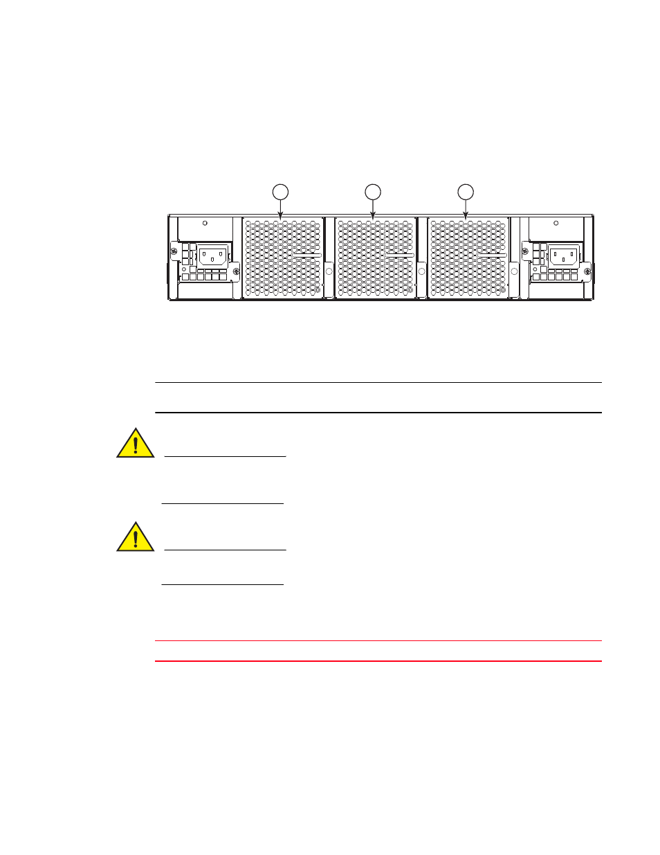
Replacing a fan assembly FRU in the Brocade VDX 6730-76
5
Replacing a fan assembly FRU in the Brocade VDX 6730-76
The Brocade VDX 6730-76 has three fan assemblies as displayed in
. The Network OS
identifies the fan locations from left to right as fan assembly #3, fan assembly #2, and fan
assembly #1.
FIGURE 18
Brocade VDX 6730-76 fan assemblies on the non-port side
ATTENTION
Maintain all power supply and fan assemblies in operational condition to provide redundancy.
CAUTION
Because the cooling system relies on pressurized air, do not leave any of the power supply and
fan assembly slots empty longer than two minutes while the switch is operating. If a power supply
or fan assembly fails, leave it in the switch until it can be replaced.
CAUTION
Disassembling any part of the power supply and fan assembly voids the warranty and regulatory
certifications. There are no user-serviceable parts inside the power supply and fan assembly.
describes the fan assembly status LED colors, behaviors, and actions required, if any.
1
Fan assembly #3
2
Fan assembly #1
3
Fan assembly #2
1
2
3
TABLE 8
Brocade VDX 6730-76 fan assembly status LED behavior, description, and required
actions
LED color and behavior
Description
Action required
Off (no light)
Fan assembly is not receiving power.
Verify that the fan assembly is
seated correctly.