Views of the brocade vdx 6730-76 switch, Figure 1, Port – Brocade VDX 6730 Hardware Reference Manual (Supporting VDX 6730-32 and VDX 6730-76) User Manual
Page 23: Figure 2, Non-port
Brocade VDX 6730 Hardware Reference Manual
5
53-1002389-06
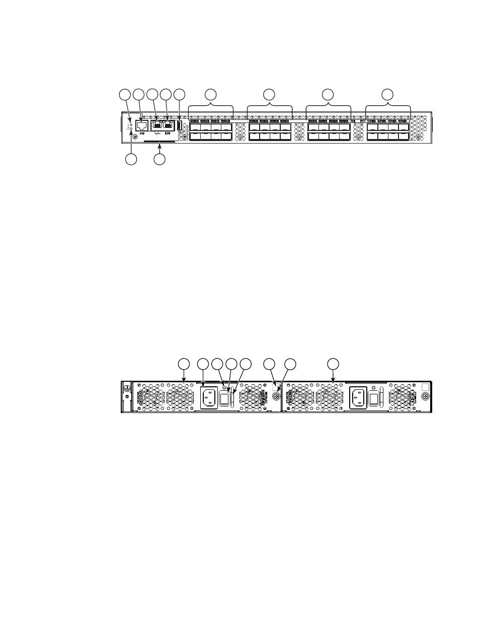
Views of the Brocade VDX 6730-76 switch
1
FIGURE 1
Port side view of the Brocade VDX 6730-32
shows the non-port side of the Brocade VDX 6730-32, which contains the combined
power supply and fan assemblies.
FIGURE 2
Non-port side view of the Brocade VDX 6730-32
Views of the Brocade VDX 6730-76 switch
The port side of the Brocade VDX 6730-76 switch includes the system LEDs, management ports
and LEDs, USB port, and Gigabit Ethernet (GbE) ports and the corresponding port status LEDs.
shows the port side of the Brocade VDX 6730-76.
1
System status LED
7
10 GbE ports 9-16 (9-12 on top, 13-16 below) with
status LEDs above
2
Serial console port (RJ45)
8
10 GbE ports 17-24 (17-20 on top, 21-24 below)
with status LEDs above
3
Ethernet management port (RJ45)
9
FC ports 1-8 (1-4 on top, 5-8 below) with status
LEDs above
4
RLO management port (RJ45)
10 System power LED
5
USB port
11 Switch ID pull-out tab
6
10 GbE ports 1-8 (1-4 on top, 5-8 below) with
status LEDs above
1
Power supply and fan assemby #2
5
Handle
2
Power cord receptacle
6
Airflow label
3
Power supply and fan status LED
7
Captive screw
4
On/off switch
8
Power supply and fan assembly #1
1
3
5
2
4
6
9
7
11
10
8
2
3
7
1
5
4
8
6