Replacing a combined fru in a brocade vdx 6730-32, Figure 11, Example – Brocade VDX 6730 Hardware Reference Manual (Supporting VDX 6730-32 and VDX 6730-76) User Manual
Page 56: Figure 12
38
Brocade VDX 6730 Hardware Reference Manual
53-1002389-06
Replacing a combined FRU in a Brocade VDX 6730-32
5
You can use external labels as a guide. The power supplies and fan assemblies are labeled with an
airflow symbol on the faceplate to indicate whether the FRU takes in or exhausts air. The symbol
also appears on the top of the FRU. All FRUs in a chassis must have the same label affixed so that
airflow direction is consistent.
illustrates examples of the airflow labels.
FIGURE 11
Examples of airflow symbols
The green E symbol indicates an exhaust FRU. This unit pulls air in from the port side of the switch
and exhausts it out the non-port side. This is called front-to-back airflow or forward airflow. This
symbol should appear on FRUs with part numbers ending with -F.
The orange I symbol indicates an intake FRU. This unit pulls air in from the non-port side of the
switch and exhausts it out the port side. This is called back-to-front airflow or reverse airflow. This
symbol should appear on FRUs with part numbers ending with -R.
The show environment fan command will indicate either “forward” or “reverse” airflow.
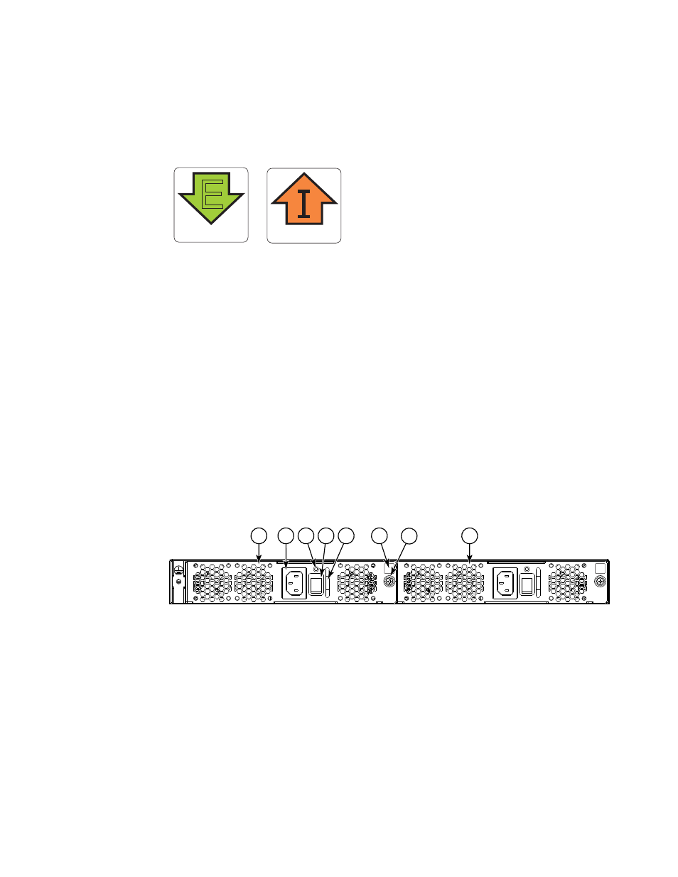
Replacing a combined FRU in a Brocade VDX 6730-32
shows the two combined AC power supply and fan assemblies in the Brocade VDX
6730-32. The Network OS identifies the FRUs from left to right as power supply and fan assembly
#2 and power supply and fan assembly #1.
shows the combined DC power supply and
fan assemblies.
FIGURE 12
Brocade VDX 6730-32 AC power supply and fan assemblies on the non-port side
AIRFLOW
E
AIRFLOW
1
Power supply and fan assembly #2
2
Handle
3
AC power cord receptacle
4
Airflow label
5
Status LED
6
Captive screw
7
On/off switch
8
Power supply and fan assembly #1
2
3
7
1
5
4
8
6