Yokogawa IR200 User Manual
Page 77
7 - 8
IM 11G02M01-01E
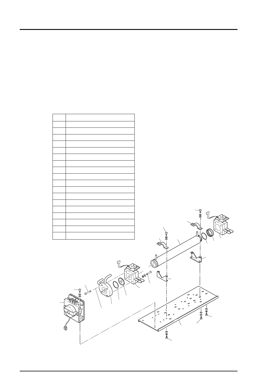
Fig. 7-3 Configuration of measuring unit (2-component analyzer: block cell + pipe cell)
16
15
11
13
12
14
12
13
11
10
3
10
17
9
1
7
8
6
5
2
5
4
18
No.
Name
1
Screw (for fixing light source unit)
2
Screw (for fixing detector)
3
Base plate
4
Light source unit
5
Screw (for fixing block cell)
6
Block cell
7
Infrared transmission window
8
O-ring
9
Detector
10
Screw (for fixing base plate)
11
Support
12
Screw (Fixing cell retainer)
13
Cell retainer
14
Pipe cell
15
O-ring
16
Infrared transmission window
17
Screw (fixing detector)
18
Detector
3) How to remove measuring unit (See Fig. 7-3)
1. For Step 1. to 4., see Item 7.5.1(1), How to remove pipe cell.5. Remove the detector output
cord connector from the printed board.
6. Remove wiring to the 2-pin terminals of the infrared ray light source assembly and chopper
motor pin connector (No. 8) from the printed board.
7. Detach the 4 screws (No. 3) fastening the base plate (No. 4) to remove the measuring unit.
Note) Special care should be taken when assembling or disassembling the measuring cell
to avoid the application of force to the detector pipe or infrared ray light source unit
pipe. If the pipe is deformed or damaged by excessive force, there is a danger of gas
leak, thus resulting in misoperation.