About fieldbus, 1 outline, 2 internal structure of eja – Yokogawa EJA115 User Manual
Page 18: 1 system/network management vfd, 2 function block vfd, 3 logical structure of each block, 4 wiring system configuration, About fieldbus -1, Outline -1, Internal structure of eja -1
IM 01C22T02-01E
3-1
3. ABOUT FIELDBUS
3.
ABOUT FIELDBUS
3.1 Outline
Fieldbus is a bi-directional digital communication
protocol for field devices, which offers an advancement in
implementation technologies for process control systems
and is widely employed by numerous field devices.
EJA Series Fieldbus communication type employs the
specification standardized by The Fieldbus Foundation,
and provides interoperability between Yokogawa
devices and those produced by other manufacturers.
Fieldbus comes with software consisting of two AI
function blocks, providing the means to implement a
flexible instrumentation system.
For information on other features, engineering, design,
construction work, startup and maintenance of
Fieldbus, refer to “Fieldbus Technical Information” (TI
38K03A01-01E).
3.2 Internal Structure of EJA
The EJA contains two virtual field devices (VFD) that
share the following functions.
3.2.1 System/network Management VFD
• Sets node addresses and Phisical Device tags (PD
Tag) necessary for communication.
• Controls the execution of function blocks.
• Manages operation parameters and communication
resources (Virtual Communication Relationship:
VCR).
3.2.2 Function Block VFD
(1)Resource block
• Manages the status of EJA hardware.
• Automatically informs the host of any detected
faults or other problems.
(2)Transducer block
• Converts sensor output to pressure signals and
transfers to AI function block.
(3)AI1 function block
• Conditions raw data from the Transducer block.
• Outputs differential pressure signals.
• Carries out scaling, damping and square root
extraction.
(4)AI2 function block
• Outputs static pressure signals.
(5)PID function block
• Performs the PID control computation based on the
deviation of the measured value from the setpoint.
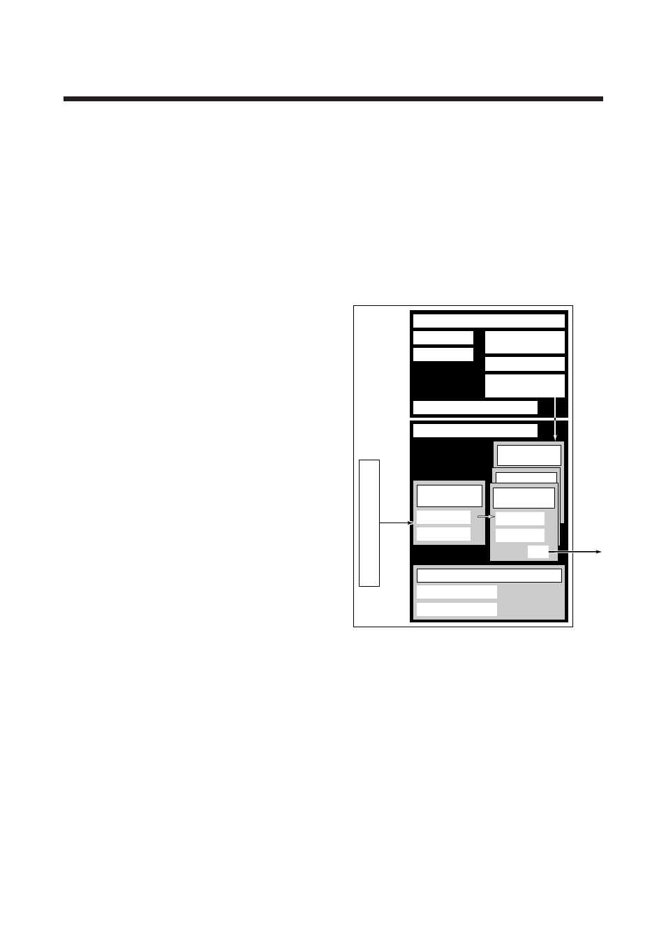
3.3 Logical Structure of Each
Block
F0301.EPS
EJA
Fieldbus
System/network management VFD
Function block VFD
Link Master (option)
PD Tag
Sensor
input
Resource block
Block tag
Parameters
PID function
block (option)
Communication
parameters
VCR
Node address
Function block
execution schedule
AI function
block
Output
AI function
block
Block tag
OUT
Parameters
Transducer
block
Block tag
Parameters
Sensor
Figure 3.1 Logical Structure of Each Block
Setting of various parameters, node addresses, and PD
Tags shown in Figure 3.1 is required before starting
operation.
3.4 Wiring System Configuration
The number of devices that can be connected to a
single bus and the cable length vary depending on
system design. When constructing systems, both the
basic and overall design must be carefully considered
to achieve optimal performance.