4 serial device connection, 1 db-9 serial port connection, Figure 4-17: lan connection – IEI Integration AFL2-08A-N26 User Manual
Page 54
AFL2-08A-N26
P a g e 38
S te p 2:
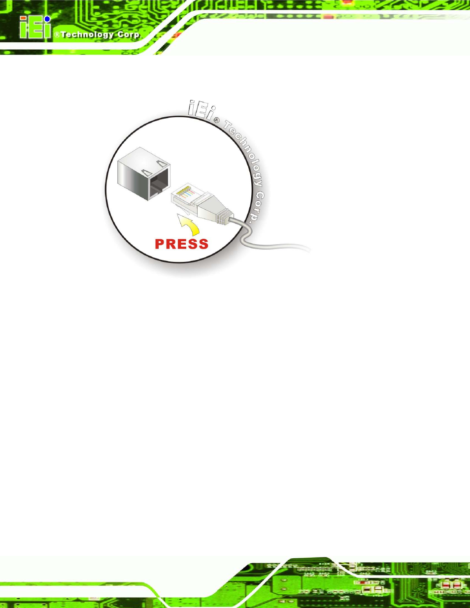
Align the connector. Align the RJ-45 connector on the LAN cable with the
RJ-45 connector on the AFL2-08A-N26. See Figure 4-17.
Figure 4-17: LAN Connection
S te p 3:
Insert the LAN cable RJ-45 connector. Once aligned, gently insert the LAN
cable RJ-45 connector into the external interface.
4.12.4 S e ria l De vic e Co n n e c tio n
There is one external RS-232 DB-9 connector and one RS-422/485 RJ-11 connector for
serial device connection. Follow the steps below to connect a serial device to the
AFL2-08A-N26.
4.12.4.1 DB-9 S e ria l P o rt Co n n e c tio n
Follow the steps below to connect a serial device to the DB-9 connector of the
AFL2-08A-N26 panel PC.
S te p 1:
Locate the DB-9 connector. The location of the DB-9 connector is shown in
Chapter 1.
- UPC-V312-D525 v1.02 (176 pages)
- UPC-V312-D525 v1.10 (175 pages)
- UPC-12A_GM45 v1.00 (147 pages)
- UPC-12A_GM45 v2.00 (144 pages)
- UPC-12A_GM45 v2.10 (145 pages)
- UPC-V315-NM70 (148 pages)
- UPC-V315-Screw Driver (1 page)
- UPC-V315-QM77 (148 pages)
- S12ASR v1.12 (110 pages)
- S12ASR v3.00 (118 pages)
- PPC-5xxx-9455 v1.00 (198 pages)
- PPC-5xxx-9455 v1.10 (198 pages)
- PPC-WIDS-51xxA-G41 (152 pages)
- PPC-51xxA-H61 (193 pages)
- PPC-5152-D525 v1.02 (183 pages)
- PPC-5152-D525 v2.10 (185 pages)
- PPC-37xxA-N26 v1.00 (203 pages)
- PPC-37xxA-N26 v1.10 (200 pages)
- PPC-37xx-N270 v1.01 (165 pages)
- PPC-37xx-N270 v2.00 (155 pages)
- PPC-37xx-N270 v2.11 (155 pages)
- PPC-37xx-N270 v2.20 (162 pages)
- ACT-457A (67 pages)
- AFL-4 series-N270 v1.05 (165 pages)
- AFL-4 series-N270 v2.10 (166 pages)
- AFL-4 series-N270 v2.11 (168 pages)
- AFL-4 series-N270 v2.20 (168 pages)
- AFL-W19A_W19B_17D_W15A-GM45 v2.10 (138 pages)
- AFL-W19A_W19B_17D_W15A-GM45 v1.06 (138 pages)
- AFL-W19A_W19B_17D_W15A-GM45 v2.20 (151 pages)
- AFL-W15A_17D-GM45 v3.00 (148 pages)
- AFL-15i-HM55 v1.01 (139 pages)
- AFL-19i-HM55 v2.00 (140 pages)
- AFL-15i-HM55 v1.20 (143 pages)
- AFL-W19A_W19B_17D_W15A-N270 v1.06 (125 pages)
- AFL-W19A_W19B_17D_W15A-N270 v2.20 (124 pages)
- AFL-W19A_17D_W15A-N270 v3.00 (126 pages)
- AFL-15A_15AE-N270_UMN_v1.01.pdf (158 pages)
- AFL-15A-N270 v1.03 (159 pages)
- AFL-15A-N270 v2.10 (159 pages)
- AFL-15A-N270 v2.20 (158 pages)
- AFL-xxA-N26 (152 pages)
- AFL-xxA-N270-Series v1.03 (171 pages)
- AFL-xxA-N270-Series v2.00 (171 pages)
- AFL-xxA-N270-Series v2.11 (170 pages)