5 jumper settings, Umper, Ettings – IEI Integration IBX-530B-N270 User Manual
Page 31: Table 3-1: jumpers
IBX-530B-270 Embedded System
Page 19
3.5 Jumper Settings
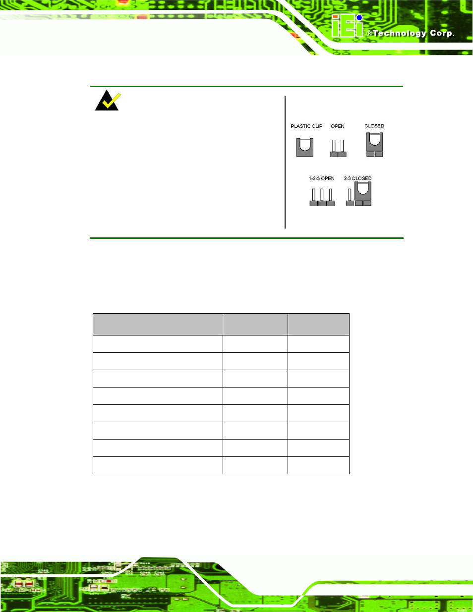
NOTE:
A jumper is a metal bridge used to close an
electrical circuit. It consists of two or three metal
pins and a small metal clip (often protected by a
plastic cover) that slides over the pins to connect
them. To CLOSE/SHORT a jumper means
connecting the pins of the jumper with the plastic
clip and to OPEN a jumper means removing the
plastic clip from a jumper.
The following jumpers can be found on the motherboard installed in the IBX-530B-N270.
Before the IBX-530B-N270 is installed, the jumpers must be set in accordance with the
desired configuration. The jumpers on the IBX-530B-N270 motherboard are listed in
Description
Label
Type
AT/ATX mode select
JP4
2-pin header
CF mode select
JCF1
2-pin header
Clear CMOS
J_COMS1
2-pin header
COM1 Pin 9 setting
JP8
10-pin header
COM3 Pin 9 setting
JP10
6-pin header
COM3 RX RS-232/422/485 select
JP9
8-pin header
COM3 TX RS-422/485 select
JP11
6-pin header
COM3 RS-232/422/485 select
JP6
12-pin header
Table 3-1: Jumpers