IEI Integration IBX-530B-N270 User Manual
Page 122
IBX-530B-270 Embedded System
Page 110
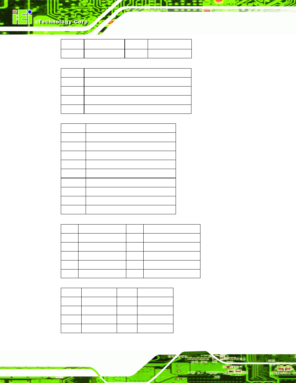
7 H_SYNC 8 V_GND
9 V_SYNC 10
V_GND
Table
e
B-6: CRT Connector Pinouts (CN4)
Pin No.
Description
1 AUD_OUTL
2 AGND_AMP
3 LINEOUT_JD
4 AUD_OUTR
Table
e
B-7: Audio Line-Out Connector Pinouts (CN3)
PIN NO.
DESCRIPTION
1 GND
2 STXP_0
3 STXN_0
4 GND
5 SRXN_0
6 SRXP_0
7 GND
8 GND
9 GND
Table
e
B-8: External SATA Connector Pinouts (SATA2)
Pin Description
Pin Description
1 PW_LED
+5V
2 +5V
3 GND
4 HD_LED
5
SUS PWR LED +5V
6
RST_SW
7 GND
8 GND
9 PW_BN
10
GND
Table
e
B-9: System Panel Connector Pinouts (JP2)
PIN NO. DESCRIPTION PIN NO. DESCRIPTION
1 +5Vsus 2 GND
3 D0F-
4 D1F+
5 D0F+
6 D1F-
7 GND
8 +5Vsus
Table
e
B-10: USB Connector Pinouts (USB1)
See also other documents in the category IEI Integration Computer Accessories:
- KM-088G (5 pages)
- ECW-281B_D2550 (159 pages)
- ECW-281B_B2-N270 v3.01 (189 pages)
- ECW-281B_B2-N270 v2.00 (180 pages)
- ECW-281B_B2-N270 v2.10 (179 pages)
- ECW-281B_B2-D525 (137 pages)
- uIBX-200-VX800 v1.04 (113 pages)
- uIBX-200-VX800 v2.00 (116 pages)
- uIBX-200-VX800 v2.10 (116 pages)
- uIBX-200 v1.02 (109 pages)
- uIBX-200 v1.10 (113 pages)
- uIBX-210-CV-N2600 (163 pages)
- TANK-101B-D525_N455 v1.02 (119 pages)
- TANK-101B-D525_N455 v1.00 (118 pages)
- TANK-101B-D525_N455 v1.10 (119 pages)
- TANK-800-D525 v1.00 (116 pages)
- TANK-800-D525 v1.14 (137 pages)
- TANK-600-D2550_N2600 (132 pages)
- TANK-GM45A (104 pages)
- TANK-700-QM67 v1.00 (128 pages)
- TANK-700-QM67 v1.12 (145 pages)
- TANK-700-QM67 v2.00 (144 pages)
- TANK-720-Q67 (147 pages)
- TANK-820-H61 v1.00 (158 pages)
- TANK-820-H61 v2.00 (158 pages)
- TANK-820-H61 v2.03 (157 pages)
- TANK-6000-C226 (138 pages)
- IDS-H61 (72 pages)
- IOPS-Q67_H61 (70 pages)
- ECN-680A-H61 (190 pages)
- ECN-780-Q67 (184 pages)
- ECN-360A-HM65 (154 pages)
- ECN-360A-D2550 (141 pages)
- EBC-2102 (5 pages)
- ECN-581A-R10-HM551 (6 pages)
- EBC-3200 (6 pages)
- EBC-3100 (8 pages)
- EBC-3000 (7 pages)
- EBC-2100 (4 pages)
- EBC-3620 (8 pages)
- VSTAND (1 page)
- AUPS-C20 v1.01 (49 pages)
- AUPS-C20 v1.02 (55 pages)
- AUPS UART Protocal SPC (11 pages)