2 front panel connectors and indicators, Figure 2-2: ibx-530b-n270 front panel – IEI Integration IBX-530B-N270 User Manual
Page 20
IBX-530B-270 Embedded System
Page 8
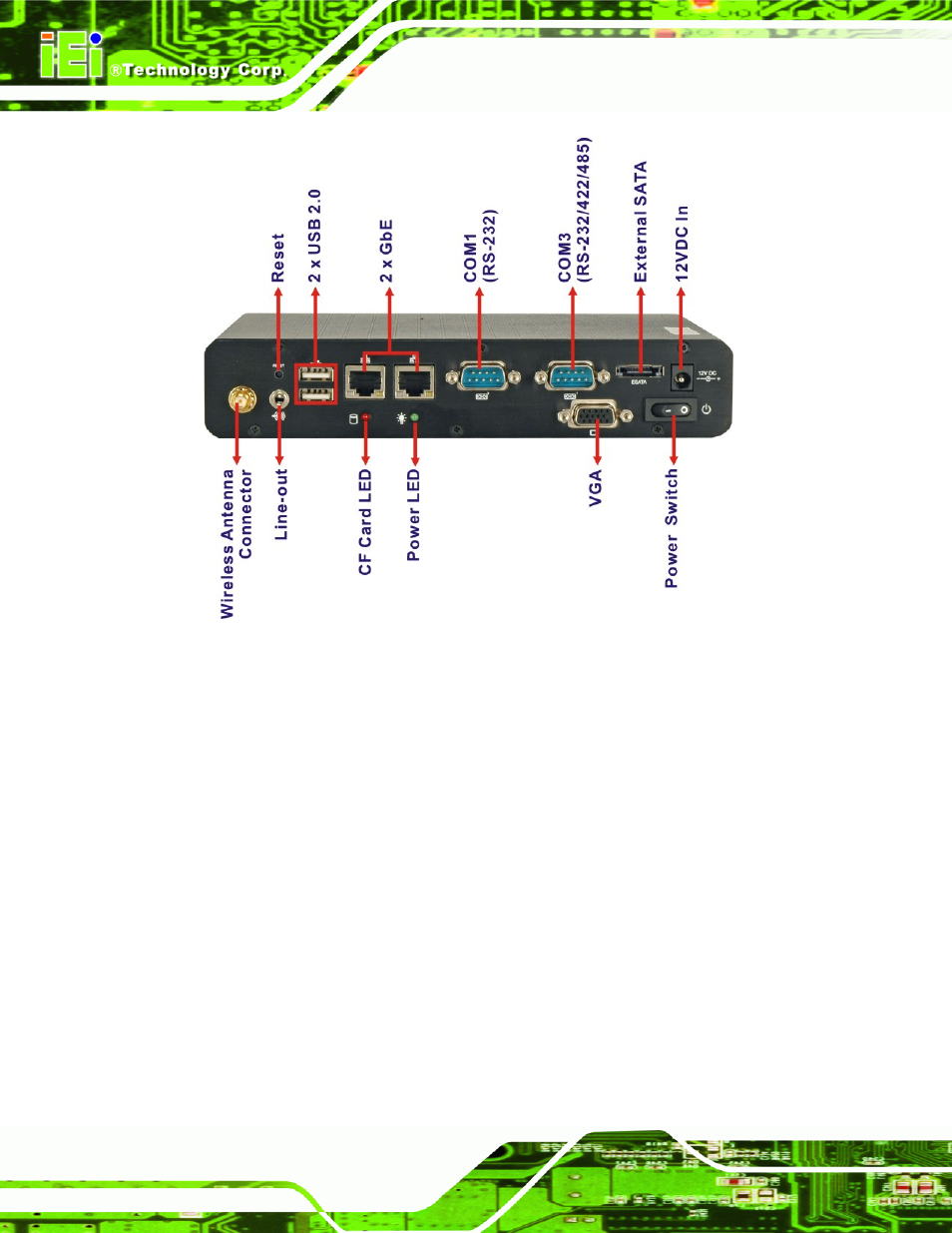
Figure 2-2: IBX-530B-N270 Front Panel
2.3.1.2 Front Panel Connectors and Indicators
The connectors, indicators and switches listed in this section are shown in Figure 2-2
above. The front panel I/O connectors are listed below:
1 x Line-out audio connector
1 x Wireless antenna connector (optional)
2 x USB 2.0 ports
2 x RJ-45 GbE connectors
1 x RS-232 serial port connector
1 x RS-232/422/485 serial port connector
1 x VGA connector
1 x External SATA connector
1 x 12V DC inlet
See also other documents in the category IEI Integration Computer Accessories:
- KM-088G (5 pages)
- ECW-281B_D2550 (159 pages)
- ECW-281B_B2-N270 v3.01 (189 pages)
- ECW-281B_B2-N270 v2.00 (180 pages)
- ECW-281B_B2-N270 v2.10 (179 pages)
- ECW-281B_B2-D525 (137 pages)
- uIBX-200-VX800 v1.04 (113 pages)
- uIBX-200-VX800 v2.00 (116 pages)
- uIBX-200-VX800 v2.10 (116 pages)
- uIBX-200 v1.02 (109 pages)
- uIBX-200 v1.10 (113 pages)
- uIBX-210-CV-N2600 (163 pages)
- TANK-101B-D525_N455 v1.02 (119 pages)
- TANK-101B-D525_N455 v1.00 (118 pages)
- TANK-101B-D525_N455 v1.10 (119 pages)
- TANK-800-D525 v1.00 (116 pages)
- TANK-800-D525 v1.14 (137 pages)
- TANK-600-D2550_N2600 (132 pages)
- TANK-GM45A (104 pages)
- TANK-700-QM67 v1.00 (128 pages)
- TANK-700-QM67 v1.12 (145 pages)
- TANK-700-QM67 v2.00 (144 pages)
- TANK-720-Q67 (147 pages)
- TANK-820-H61 v1.00 (158 pages)
- TANK-820-H61 v2.00 (158 pages)
- TANK-820-H61 v2.03 (157 pages)
- TANK-6000-C226 (138 pages)
- IDS-H61 (72 pages)
- IOPS-Q67_H61 (70 pages)
- ECN-680A-H61 (190 pages)
- ECN-780-Q67 (184 pages)
- ECN-360A-HM65 (154 pages)
- ECN-360A-D2550 (141 pages)
- EBC-2102 (5 pages)
- ECN-581A-R10-HM551 (6 pages)
- EBC-3200 (6 pages)
- EBC-3100 (8 pages)
- EBC-3000 (7 pages)
- EBC-2100 (4 pages)
- EBC-3620 (8 pages)
- VSTAND (1 page)
- AUPS-C20 v1.01 (49 pages)
- AUPS-C20 v1.02 (55 pages)
- AUPS UART Protocal SPC (11 pages)