B.1 peripheral interface connectors, Eripheral, Nterface – IEI Integration IBX-530B-N270 User Manual
Page 120: Onnectors
IBX-530B-270 Embedded System
Page 108
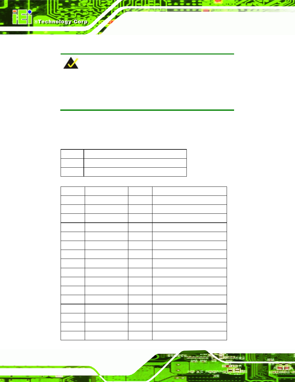
B.1 Peripheral Interface Connectors
NOTE:
The jumpers and connectors shown in the section below are those
jumpers and connectors that are relevant to the configuration and
installation of the embedded system.
The IBX-530B-N270 embedded system motherboard, the AFLMB-945GSE comes with a
number of peripheral interface connectors. The pinouts for the connectors that are used in
the IBX-530B-N270 are listed below:
PIN NO.
DESCRIPTION
1 Battery
+3.3V
2 GND
Table
e
B-1: Battery Connector Pinouts (BT1)
Pin No.
Description
Pin No.
Description
1 GROUND 26
CD1
2 D3
27
D11
3 D4
28
D12
4 D5
29
D13
5 D6
30
D14
6 D7
31
D15
7 CE
32
CE2
8 A10
33
VS1
9 OE
34
IOR
10 A9
35 IOW
11 A8
36 WE
12 A7
37 IRQ
13 VCC1
38 VCC
14 A6
39 CSEL
15 A5
40 VS2
16 A4
41 RESET
- KM-088G (5 pages)
- ECW-281B_D2550 (159 pages)
- ECW-281B_B2-N270 v3.01 (189 pages)
- ECW-281B_B2-N270 v2.00 (180 pages)
- ECW-281B_B2-N270 v2.10 (179 pages)
- ECW-281B_B2-D525 (137 pages)
- uIBX-200-VX800 v1.04 (113 pages)
- uIBX-200-VX800 v2.00 (116 pages)
- uIBX-200-VX800 v2.10 (116 pages)
- uIBX-200 v1.02 (109 pages)
- uIBX-200 v1.10 (113 pages)
- uIBX-210-CV-N2600 (163 pages)
- TANK-101B-D525_N455 v1.02 (119 pages)
- TANK-101B-D525_N455 v1.00 (118 pages)
- TANK-101B-D525_N455 v1.10 (119 pages)
- TANK-800-D525 v1.00 (116 pages)
- TANK-800-D525 v1.14 (137 pages)
- TANK-600-D2550_N2600 (132 pages)
- TANK-GM45A (104 pages)
- TANK-700-QM67 v1.00 (128 pages)
- TANK-700-QM67 v1.12 (145 pages)
- TANK-700-QM67 v2.00 (144 pages)
- TANK-720-Q67 (147 pages)
- TANK-820-H61 v1.00 (158 pages)
- TANK-820-H61 v2.00 (158 pages)
- TANK-820-H61 v2.03 (157 pages)
- TANK-6000-C226 (138 pages)
- IDS-H61 (72 pages)
- IOPS-Q67_H61 (70 pages)
- ECN-680A-H61 (190 pages)
- ECN-780-Q67 (184 pages)
- ECN-360A-HM65 (154 pages)
- ECN-360A-D2550 (141 pages)
- EBC-2102 (5 pages)
- ECN-581A-R10-HM551 (6 pages)
- EBC-3200 (6 pages)
- EBC-3100 (8 pages)
- EBC-3000 (7 pages)
- EBC-2100 (4 pages)
- EBC-3620 (8 pages)
- VSTAND (1 page)
- AUPS-C20 v1.01 (49 pages)
- AUPS-C20 v1.02 (55 pages)
- AUPS UART Protocal SPC (11 pages)