3 internal peripheral connectors, 1 atx power connector, Nternal – IEI Integration ECW-281B_B2-D525 User Manual
Page 30: Eripheral, Onnectors, Figure 3-2: atx power connector location, Table 3-1: peripheral interface connectors
ECW-281B/B2-D525 Embedded System
Page 17
Power button connector
2-pin wafer
PWR_BTN
Reset button connector
2-pin header
RST_BTN
Serial ATA (SATA) drive connectors
7-pin SATA
SATA1
RS-232 serial port connector (COM3 – COM6)
40-pin header
COM
RS-232/422/485 serial port connector
14-pin header
COM2
USB 2.0 connector
8-pin header
USB4
Table 3-1: Peripheral Interface Connectors
3.3 Internal Peripheral Connectors
Internal peripheral connectors are found on the motherboard and are only accessible
when the motherboard is outside of the chassis. This section has complete descriptions of
the internal, peripheral connectors on the WAFER-PV-D5252 that are used for the
ECW-281B/B2-D525.
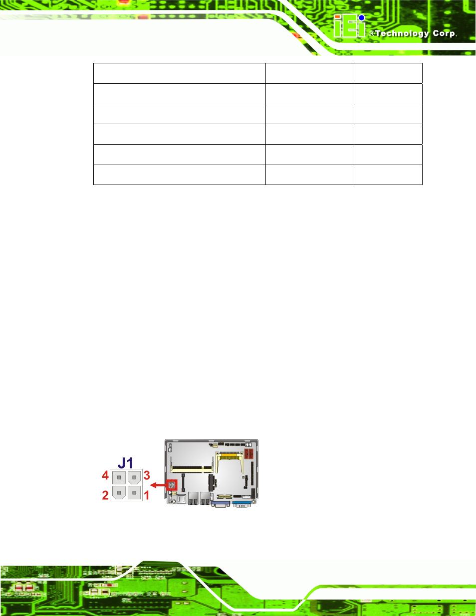
3.3.1 ATX Power Connector
CN Label:
J1
CN Type:
4-pin power connector (1x4)
CN Location:
See
655
Figure 3-2
CN Pinouts:
See
755
Table 3-2
The 4-pin ATX power connector is connected to a DC-DC power module.
Figure 3-2: ATX Power Connector Location