3 so-dimm installation – IEI Integration NANO-HM651 User Manual
Page 54
NANO-HM651 EPIC SBC
Page 40
Before and during the installation of the NANO-HM651 DO NOT:
Remove any of the stickers on the PCB board. These stickers are required for
warranty validation.
Use the product before verifying all the cables and power connectors are
properly connected.
Allow screws to come in contact with the PCB circuit, connector pins, or its
components.
4.3 SO-DIMM Installation
WARNING:
Using incorrectly specified SO-DIMM may cause permanently damage
the NANO-HM651. Please make sure the purchased SO-DIMM
complies with the memory specifications of the NANO-HM651.
SO-DIMM specifications compliant with the NANO-HM651 are listed in
the specification table of Chapter 1.
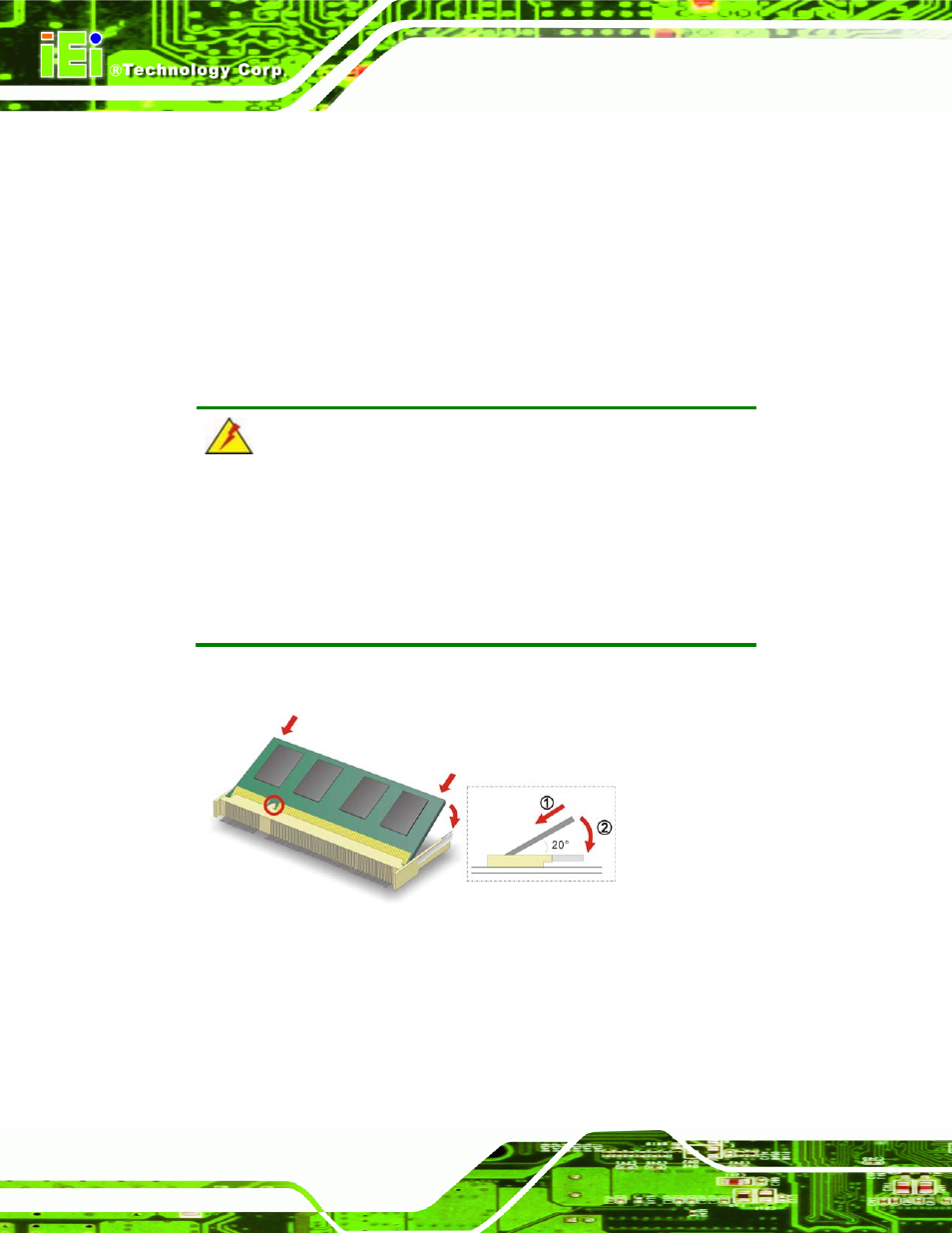
To install an SO-DIMM, please follow the steps below and refer to Figure 4-1.
Figure 4-1: SO-DIMM Installation
Step 1:
Locate the SO-DIMM socket. Place the board on an anti-static mat.
Step 2:
Align the SO-DIMM with the socket. Align the notch on the memory with the
notch on the memory socket.
Step 3:
Insert the SO-DIMM. Push the memory in at a 20º angle. (See Figure 4-1)