2 peripheral interface connectors, Table 3-1: peripheral interface connectors – IEI Integration KINO-DH610 User Manual
Page 28
KINO-DH610
Page 16
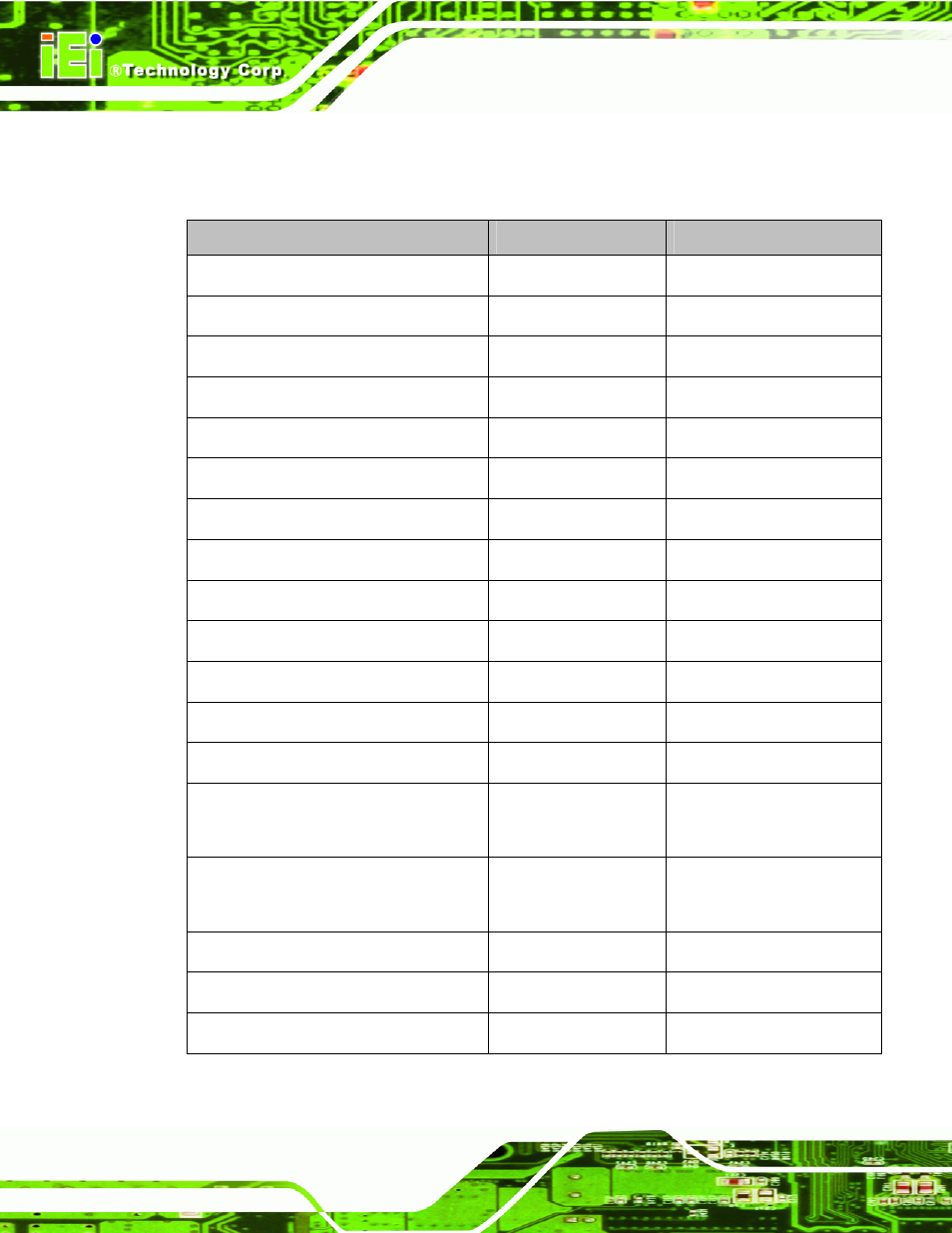
3.1.2 Peripheral Interface Connectors
The table below lists all the connectors on the board.
Connector
Type
Label
Battery connector
2-pin wafer
BAT2
BIOS update connector
6-pin header
SPI1
DDR3 SO-DIMM slots
DDR3 SO-DIMM slot
CHA_DIMM1,CHB_DIMM1
Debug port connector
18-pin header
CN8
Digital I/O connector
10-pin header
DIO2
EC update connector
6-pin header
JSPI2
Fan connector (CPU)
4-pin wafer
CPU_FAN1
Fan connector (PCH)
3-pin wafer
PCH_FAN1
Front Panel connector
10-pin header
F_PANEL
Keyboard and mouse connector
6-pin wafer
KB_MS_CN2
PCI slot
PCI slot
PCI1
PCIe x1 slot
PCIe x1 slot
PCIE1
Power connector
4-pin header
DC_IN2
SATA drive connector
Serial ATA (SATA)
3Gb/s Connector
SATA1, SATA2, SATA3,
SATA4
SATA power connector
2-pin wafer
SATA_PWR1,
SATA_PWR2
Serial port connector (RS-232/422/485)
14-pin header
COM3
TPM connector
20-pin connector
TPM1
USB connector
8-pin header
USB2, USB3, USB4
Table 3-1: Peripheral Interface Connectors