5 cpu card installation, 3 jumper settings, Umper – IEI Integration PCIE-G41A2 User Manual
Page 55: Ettings
PCIE-G41A2 PICMG 1.3 CPU card
Page 43
NOTE:
IEI has a wide range of backplanes available. Please contact your
PCIE-G41A2 vendor, reseller or and IEI sales representative at
or visit the IEI website at
find out more about the available chassis.
4.2.5 CPU Card Installation
To install the PCIE-G41A2 CPU card onto the backplane, carefully align the CPU card
interface connectors with the corresponding socket on the backplane. To do this, please
refer to the reference material that came with the backplane. Next, secure the CPU card to
the chassis. To do this, please refer to the reference material that came with the chassis.
4.3 Jumper Settings
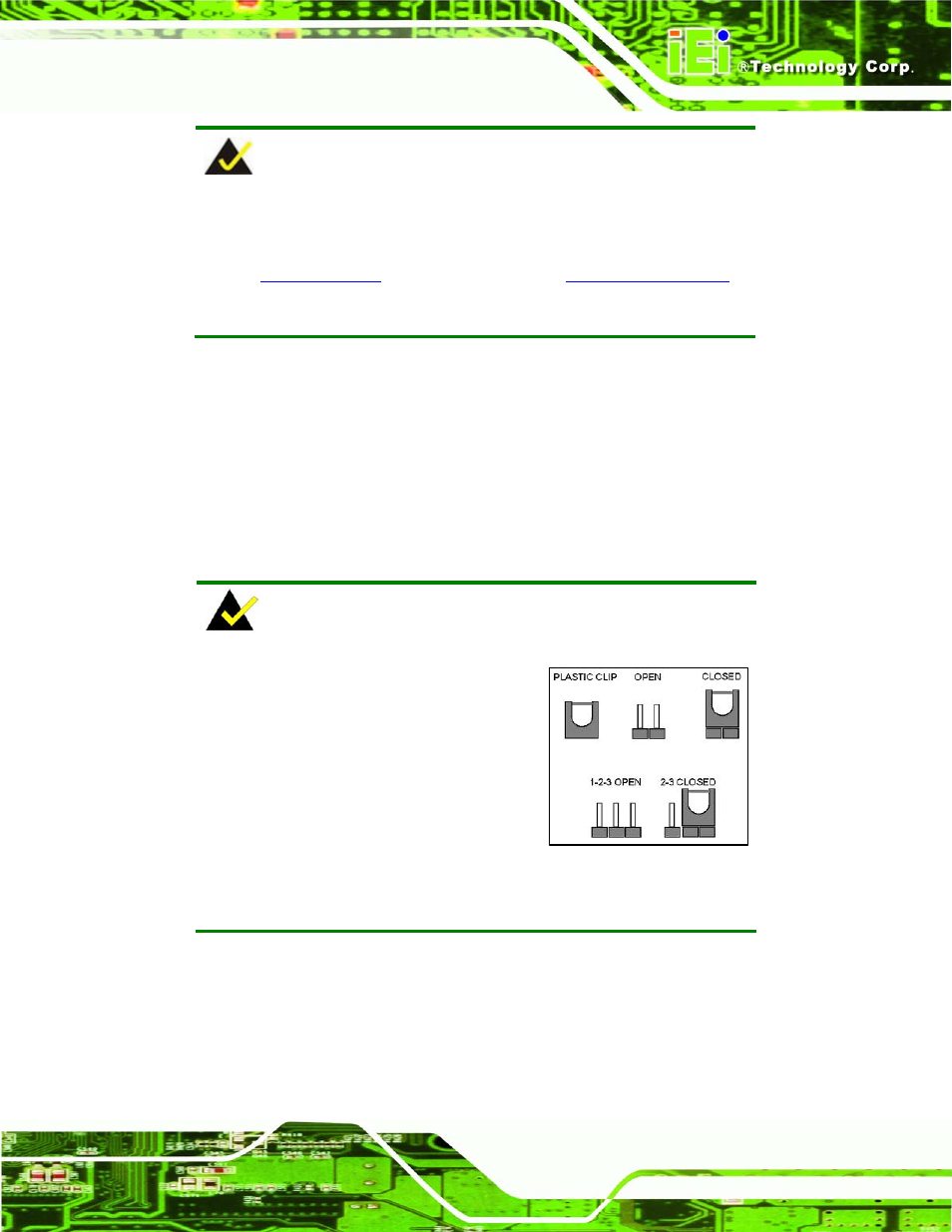
NOTE:
A jumper is a metal bridge used to close
an electrical circuit. It consists of two or
three metal pins and a small metal clip
(often protected by a plastic cover) that
slides over the pins to connect them. To
CLOSE/SHORT a jumper means
connecting the pins of the jumper with
the plastic clip and to OPEN a jumper means removing the plastic clip
from a jumper.
The PCIE-G41A2 includes one jumper shown in Table 4-1.