System overview – Warner Electric FM Series Foot Mounted Load Cells AC10 Measuring System A-B-C30 User Manual
Page 9
9
Warner Electric • 800-825-9050
P-2012-2
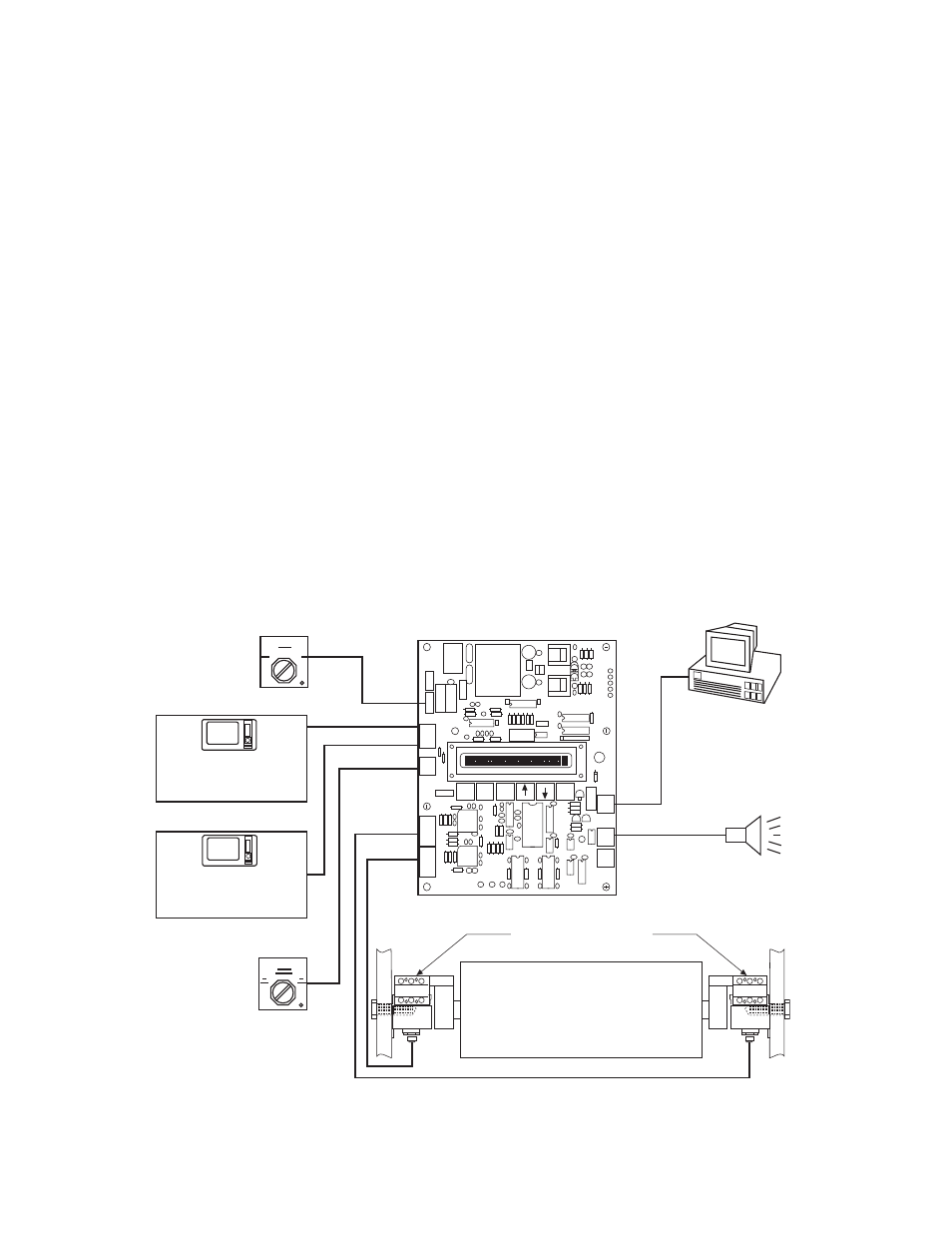
System Overview
The AC10 Tension Measuring System is designed
to measure tension on continuous strip process-
ing lines and equipment. The system consists of
two AC10 Tensioncells, the PSAC10 power supply
amplifier board, and two cables for connecting the
Tensioncells to the board.
AC10 Tensioncells are mounted in pairs, one at
each end of the measuring roll. During operation
the Tensioncells continuously measure the
mechanical tension force applied to the measuring
roll. When the force is applied, the load plate
deflects toward or away from the base block
depending on the resultant force acting upon the
Tensioncell. Deflection toward the base block is
defined as the "Compression Mode.” Deflection
away from the base block is defined as the
"Tension Mode." AC10 Tensioncells work equally
well in either mode.
The mechanical deflection of the load plate is
converted into an electrical output signal by the
AC Linear Variable Differential Transformer
(LVDT). Displacement of the LVDT core caused
by variations in web tension results in an output
signal to the PSAC10 board directly proportional
to the applied tension.
The analog outputs from the Tensioncells are con-
verted into digital signals by the microprocessor-
based electronics. The signals are conditioned,
processed, and summed to produce two individu-
ally scaleable, -10 to +10 volt DC analog outputs
to a tension indicator, drive or a MCS2000 CTDA
control which can be used to monitor or control
tension. The percent tension applied to each
Tensioncell and the total tension are displayed on
the board mounted 16-character liquid crystal
display (LCD).
Terminals are also provided for connecting a user
supplied On/Off power switch, 1-only 2-only
switch, and RS-422 PC interface. A threshold
alarm relay connection is also provided.
J3
J4
J6
J5
Warner
Part# 80-165 Rev
Serial#
Setup
Rapid
Exit
Setup
Enter
J7
J8
J9
J1
J2
PSAC10 Board
Power
Switch
Output #1
Output #2
Control
Analog or Digital
Meter
Drive
Cell #1/Total/Cell #2
Switch
AC-10 Tensioncells
Threshold
Alarm
RS-422
Interface
MCS2000-CTDA
MCS2000-CTDA
Control
Analog or Digital
Meter
Drive
Note: When using the PSAC10 board, connect the outputs to the MCS2000 CTDA. There is no
need to use the MCS2000 CTLC, because the signal is amplified and summed in the PSAC10.