Warner Electric FM Series Foot Mounted Load Cells AC10 Measuring System A-B-C30 User Manual
Page 35
35
Warner Electric • 800-825-9050
P-2012-3
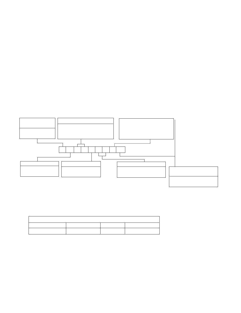
Shaft Mounting
Configuration
W1 Split bushing
W2 Solid bushing
Electrical
Connection
B - MS Connector
Type
A - Pulley or Sheave
Series 30, Type A Specifications – Non-Rotating Shaft Mounting
Series 30, Type A – Nominal Capacity Ranges
Code
P
T U
Pounds
0-20
0-50
0-90
Series Number (2 Digits)
30 Wall Mount
B
A
3
0
T
1
6
K W1
Capacity Range
See Table 1-A
Model Number Nomenclature Example
Example Shown:
BA30T16KW1
B = MS Connector
A = Pulley Mount
30 = Series 30, Wall Mount
T = 0-50 lbs. Capacity
16 = 1” Diameter Shaft
K = K Type DC LVDT
W = Split Bushing
Note: For dual load cell applications “W1” and “W2” cell are required.
K - DC LVDT with
Maximum 3 VDC
Output Change Including
Tare Displacement
Shaft Diameter
See Table I-B for Type A
Recalibration After Installation
Wall Mounted Tensioncells can be relocated
around the center of the measuring roll. The the-
ory of this operation is explained in the
Description of Operation on Page 5. If this pro-
cedure cannot accomplish the necessary
changes because the tension requirements are
extremely different than the original application,
it will be necessary to return the Tensioncells to
the factory for new cells.
Table I-A
Note: Other load ratings are available as special order.
Contact Warner Electric for other load ranges
available.