Warner Electric FM Series Foot Mounted Load Cells AC10 Measuring System A-B-C30 User Manual
Page 20
Model
Max Load
Min. Tension
Capacity
Load for Setup
(Pounds)
(Pounds)
ACIDA
60
4
ACIDB
170
10
ACIDC
500
30
Table 2
20
Warner Electric • 800-825-9050
P-2012-2
7. Adjust Out 1 0%
a.
Connect a digital voltmeter between J6-3
Out 1 and J6-4 Gnd.
b. Press the UP or DOWN arrow key (and
RAPID key if necessary) until the desired
no load output voltage is attained.
c.
Press ENTER.
8. Adjust Out 2 0%
a.
Connect a digital voltmeter between J6-1
Out 2 and J6-2 Gnd.
b. Press the UP or DOWN arrow key (and
RAPID key if necessary) until the desired
no load output voltage is attained.
c.
Press ENTER.
Note: Steps 9 through 12 can be performed
with 50% or 100% load applied when setting
Output #1 and Output #2 voltage. Refer to
the table at the right for minimum resultant
load required for setup before proceeding.
9. Apply Load 100%
a.
Press the UP or DOWN arrow key to tog-
gle between 50% or 100%. When desired
percentage is displayed.
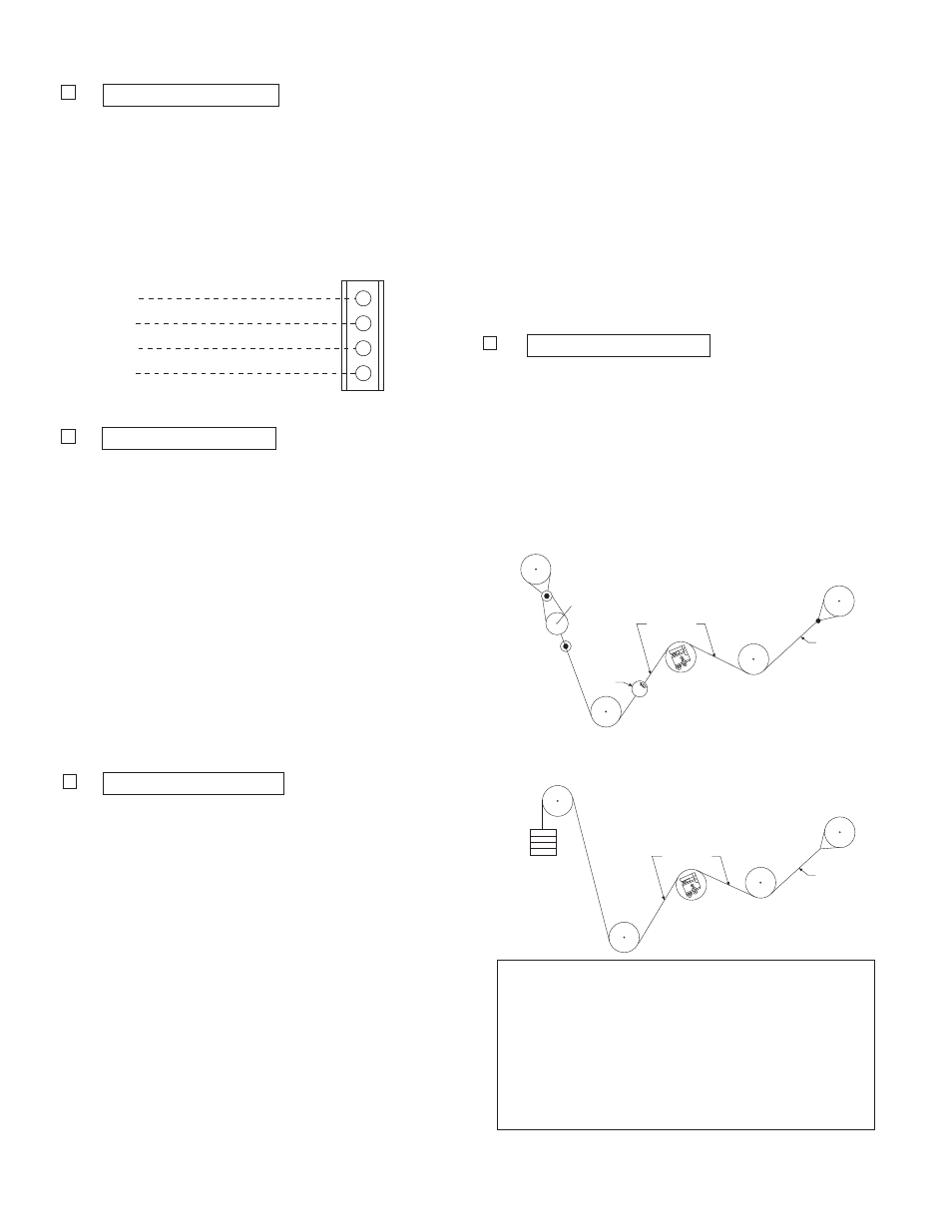
The illustrations at the right show two pull
test methods. These tests are used to
apply a load representative of the web
tension. The load should be equal to the
percentage of the full load selected (50%
or 100%).
b. Thread a non-stretchable rope over the
center of the tension measuring roll simu-
lating the web path.
Out 2
Gnd
Out 1
Gnd
J6
Output #2 ( -10 to +10 VDC)
Common
Output #1 ( -10 to + VDC)
Common
1
2
3
4
Note: All rolls used in the pull test
should be free running rolls.
c.
With one end of the rope secured, hang a
weight equal to the full load tension. (50%
if selected)
A crane scale may be used to apply the
required load.
d. Press
ENTER.
10. Adjust Out 1 100%
a.
Connect a digital voltmeter between J6-3
Out 1 and J6-4 Gnd.
b. Press the UP or DOWN arrow key (and
RAPID key if necessary) until the desired
full load output voltage is attained.
c.
Press ENTER.
Scale
W eb Path
Roll
Rope
W eb Path
Roll
Rope
W eights for
Max. Tension