Warner Electric FM Series Foot Mounted Load Cells AC10 Measuring System A-B-C30 User Manual
Page 46
46
Warner Electric • 800-825-9050
P-2012-4
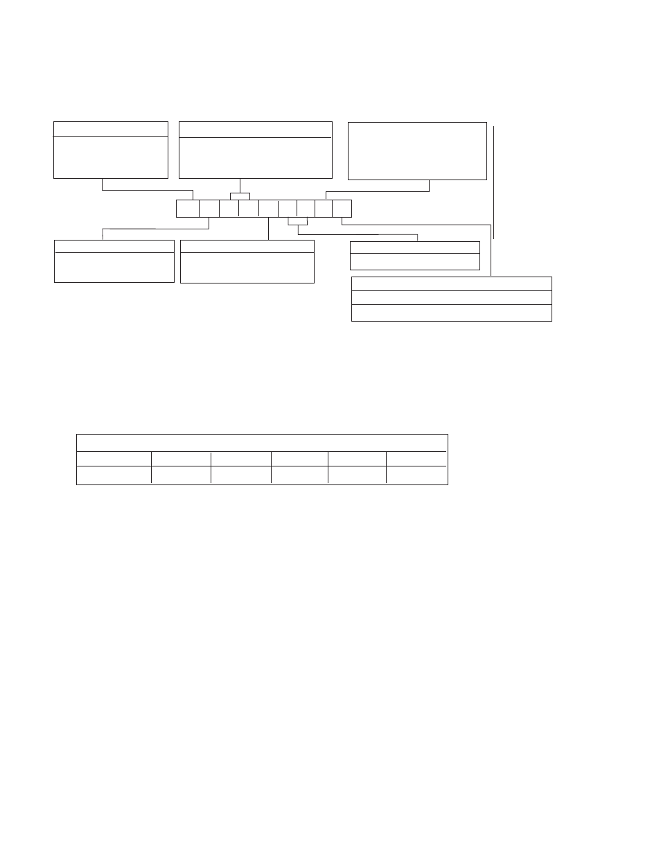
Example Shown:
BC30P16KW1
N = MS Connector
C = Rotating Shaft
30 = Series 30, Wall Mount
P = 0-20 lbs. Capacity
16 = 1” Diameter Shaft
K = K Type DC LVDT
W1 = Split Bushing
Shaft Mounting Configuration
W1-Split bushing
W2-Solid bushing
Electrical
Connection
B - MS Connector
Type
B - Non-Rotating Shaft
Series Number (2 Digits)
30 Wall Mount
B
B
3
0
P
1
6
K W1
Capacity Range
See Table II-A
K - DC LVDT with
Maximum 3 VDC Output
Change Including Tare
Displacement
Shaft Diameter
See Table ll-B
Model Number Nomenclature Example
Series 30, Type B Specifications – Non-Rotating Shaft Mounting
Series 30, Type B – Nominal Capacity Ranges
Code
P
T
U
X
Z
Pounds
0-20
0-50
0-90
0-200
0-500
Note
: Other Load ranges are available on special order. Contact Warner Electric for ratings & abalability.
Table II-A
- UNIBRAKE NEMA 4 (6 pages)
- UNIBRAKE (8 pages)
- ARC 2000 (16 pages)
- ARC Clutch_ZRC Top Load (18 pages)
- ZRC Clutch_ARC Top Load (18 pages)
- Dairy Cap Chuck (24 pages)
- Dairy Capping Headsets (10 pages)
- Autogap 475 & 650 (4 pages)
- Brushholder Installation (2 pages)
- Autogap 825-1225 (2 pages)
- Electro-Packs EP-170, 250, 400, 500, 825, 1000, 1525 (20 pages)
- Electro-Brake 375, 475, 650, 825, 1000, 1225 (20 pages)
- Electro-Clutch EC-375, EC-475, EC-650, EC-825, EC-1000, EC-1225 (20 pages)
- 5300-101-001 Collector Ring (2 pages)
- 5301-101-010 Collector Ring (2 pages)
- Brushholder Assembly and Mounting Dimensions (2 pages)
- SF_PB 400 (2 pages)
- SF_PB 250 (2 pages)
- Autogap 825-1525 (4 pages)
- Electro-Module EM-50, EM-100, EM-180, EM-210, EM-215 (22 pages)
- FB-375, 475, 650 (14 pages)
- 5200-101-012 Conduit Box Kit (4 pages)
- 5200-101-011 Conduit Box Kit (4 pages)
- 5200-101-010 Conduit Box Kit (4 pages)
- Recommended Electrical Installation Procedure for Warner Electric Clutches and Brakes (2 pages)
- EP-400 Vertical Mounting (2 pages)
- EP-250 Vertical Mounting (2 pages)
- Autogap 500 (4 pages)
- ER 825 and 1225 Normal Duty (16 pages)
- ER 825 and 1225 Heavy Duty (14 pages)
- ERS Electrically Released Brakes (6 pages)
- AT Brakes & Clutches Complete Brake Repair – On the Shaft, Sizes 25, 55, 115 (4 pages)
- AT Brakes (6 pages)
- AT Brake–Major Service Repair Instructions for Sizes 25, 55, 115 (9 pages)
- AT Clutch – Major Service Sizes 25, 55, 115 (12 pages)
- 5162-101-002 Conduit Box Kit (6 pages)
- Electrically Released Permanent Magnet Clutch Compatible Modules (4 pages)
- Electrically Released Motor Brake Module for EM-MBFB and EUM-MBFB (6 pages)
- Electrically Released Brake Module For EM-FBB and EUM-FBB (4 pages)
- Electrically Released Brake ER-375, ER-475, ER-650 (12 pages)
- Autogap 825-1525 Special Heavy Duty (4 pages)
- 5370-101-042 Conduit Box Kit (4 pages)
- Preassembled Clutch_Electrically Released Brake Module (7 pages)
- EUM-50_EUM-100_EUM-180_EUM-210_EUM-215 (16 pages)
- 5370-101-045 Conduit Box Kit (5 pages)