Warner Electric FM Series Foot Mounted Load Cells AC10 Measuring System A-B-C30 User Manual
Page 22
22
Warner Electric • 800-825-9050
P-2012-2
Troubleshooting
When properly installed in accordance with the
design specification and procedures outlined in
this manual, the AC10 Tension Measuring
System should require little or no regular main-
tenance or service. Certain conditions, however,
can impair the accuracy, reliability, and perform-
ance of the system. The following are some
conditions to consider which may effect the
mechanical and/or electrical components of the
system.
1. Have the system operating parameters
changed?
a. Has the web tension changed?
b. Does the tension plus tare load exceed
the maximum rated load capacity of the
unit?
c. Has the Wrap Angle changed?
2. Are the Tensioncells mounted correctly and
securely?
3. Is the tension measuring roll properly aligned
and does it turn freely?
4. Is the line voltage present and the on-board
Input Power Selector Switch in the correct
position?
5. Is an external power switch connected and
operating correctly? If an external switch is
not used, are the jumpers properly installed
at J4? See page 11.
6. Are all fuses and/or circuit breakers installed
and functional? There are two 250V, 500mA
fuses on the board.
7. Is the Run Mode Indicator LED flashing? If
not, check if the system is in Setup mode.
8. Is the on-board display lit? Check LCD
Brightness Adjustment.
9. Verify the following voltages.
TP3 to TP7
+10 volts DC
TP4 to TP7
+2.5 volts DC
TP5 to TP7
+15 volts DC
TP6 to TP7
+5volts DC
TP8 to TP7
-5 volts DC
TP9 to TP7
-15 volts DC
10. Are outputs responding to tension changes?
Check connections and voltages at J1, J2,
and J6.
11. Does the output signal(s) from the board
meet the voltage requirements for the
device(s) connected to it?
12. Is the Excitation Voltage to the LVDTs cor-
rect?
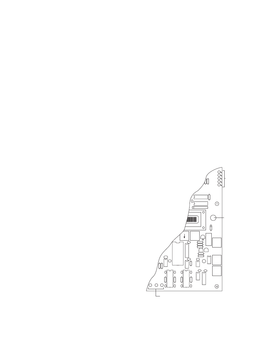
Test Points
TP5, TP6, TP7,
TP8, TP9
Enter
J7
J8
J9
LCD Brightness
Adjustment
+5VDC
-5VDC
-5VDC
+5VDC
GND
Test Points
TP2, TP3, TP4