Warner Electric FM Series Foot Mounted Load Cells AC10 Measuring System A-B-C30 User Manual
Page 24
24
Warner Electric • 800-825-9050
P-2012-2
See Note
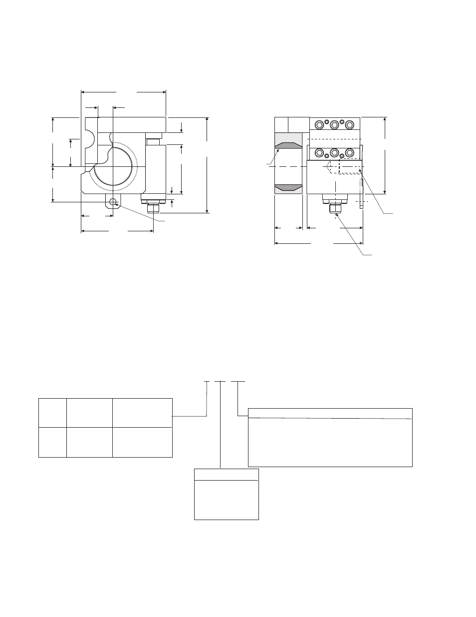
3.13
2.13
3.44
1.13
5/8-11 UNC
.93 Full Th’d
for Mounting
Bolt
Electrical
Connector
2.50
.25 Dia. Hole
For Locking
Screw
3.90
1.13
2.00
.75
3.00
Note: Stainless steel self-aligning bushing provided
for 1/2” to 1-1/2” diameter shafts in 1/16” increments.
+
.50
2.00
.25
1.31
1.44
W2 unit shown here.
W1 unit is available.
Tensioncell Model Number Designation
A C 1 0 B 1 6 W 1
Max.Load
Min.Tension
Code
Capacity
Load for Setup
Support Bushing (AC10 only)
(pounds) (pounds)
W1 = Split bushing for clamping
A
60
4
W2 = Solid bushing for expansion
B
170
10
S = System, which includes one “W1” cell,
C
500
30
one “W2” cell, two 30 ft cables and a
PSAC10 board.
Examine: AC10B16W1
Shaft Diameter
AC10 = Side Mount Tensioncell
12
3/4
B =
170 pound capacity
16
1
16 =
1 inch shaft diameter
20
1-1/4
W1 =
AC10 with split bushing
23
1-7/16
Note: Other shaft diameters are available.
(Specifications and dimensions subject to change without notice.)
AC10 Tensioncell Dimensional Drawings
- UNIBRAKE NEMA 4 (6 pages)
- UNIBRAKE (8 pages)
- ARC 2000 (16 pages)
- ARC Clutch_ZRC Top Load (18 pages)
- ZRC Clutch_ARC Top Load (18 pages)
- Dairy Cap Chuck (24 pages)
- Dairy Capping Headsets (10 pages)
- Autogap 475 & 650 (4 pages)
- Brushholder Installation (2 pages)
- Autogap 825-1225 (2 pages)
- Electro-Packs EP-170, 250, 400, 500, 825, 1000, 1525 (20 pages)
- Electro-Brake 375, 475, 650, 825, 1000, 1225 (20 pages)
- Electro-Clutch EC-375, EC-475, EC-650, EC-825, EC-1000, EC-1225 (20 pages)
- 5300-101-001 Collector Ring (2 pages)
- 5301-101-010 Collector Ring (2 pages)
- Brushholder Assembly and Mounting Dimensions (2 pages)
- SF_PB 400 (2 pages)
- SF_PB 250 (2 pages)
- Autogap 825-1525 (4 pages)
- Electro-Module EM-50, EM-100, EM-180, EM-210, EM-215 (22 pages)
- FB-375, 475, 650 (14 pages)
- 5200-101-012 Conduit Box Kit (4 pages)
- 5200-101-011 Conduit Box Kit (4 pages)
- 5200-101-010 Conduit Box Kit (4 pages)
- Recommended Electrical Installation Procedure for Warner Electric Clutches and Brakes (2 pages)
- EP-400 Vertical Mounting (2 pages)
- EP-250 Vertical Mounting (2 pages)
- Autogap 500 (4 pages)
- ER 825 and 1225 Normal Duty (16 pages)
- ER 825 and 1225 Heavy Duty (14 pages)
- ERS Electrically Released Brakes (6 pages)
- AT Brakes & Clutches Complete Brake Repair – On the Shaft, Sizes 25, 55, 115 (4 pages)
- AT Brakes (6 pages)
- AT Brake–Major Service Repair Instructions for Sizes 25, 55, 115 (9 pages)
- AT Clutch – Major Service Sizes 25, 55, 115 (12 pages)
- 5162-101-002 Conduit Box Kit (6 pages)
- Electrically Released Permanent Magnet Clutch Compatible Modules (4 pages)
- Electrically Released Motor Brake Module for EM-MBFB and EUM-MBFB (6 pages)
- Electrically Released Brake Module For EM-FBB and EUM-FBB (4 pages)
- Electrically Released Brake ER-375, ER-475, ER-650 (12 pages)
- Autogap 825-1525 Special Heavy Duty (4 pages)
- 5370-101-042 Conduit Box Kit (4 pages)
- Preassembled Clutch_Electrically Released Brake Module (7 pages)
- EUM-50_EUM-100_EUM-180_EUM-210_EUM-215 (16 pages)
- 5370-101-045 Conduit Box Kit (5 pages)