Description a. general information, B. the mechanical system – Warner Electric FM Series Foot Mounted Load Cells AC10 Measuring System A-B-C30 User Manual
Page 28
28
Warner Electric • 800-825-9050
P-2012-3
Description
A. General Information
Warner Electric Series 30 Type A Tensioncells
are force transducers, specially designed to
measure and control tension on single strand
wire, cable or filaments, on continuous strip pro-
cessing lines. They convert the mechanical
force of strand tension into an electrical signal,
which is directly proportional to the strand ten-
sion.
Type "A" Tensioncells are installed as single
units with a pulley or sheave (See Figures 1a
and Figure 1b). They are intended for NON-
ROTATING shaft installations. Tensioncells can
be provided to accept shaft sizes from 3/4 inch
to 1-7/16 inch. (See Table 1-B, Page 11)
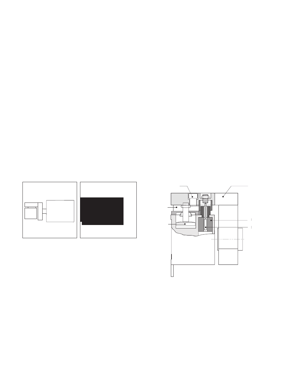
Figure 2
Damper
C-Flexure
Far Side
Mechanical Stop
Load
Plate
LVDT
L
L
LVDT
L
L
Core
Figure 1a
Figure 1b
W1
W1
B. The Mechanical System
The mechanical system consists of a Patented
"C-Flexure Pivot Assembly" which incorporates
a mounting Base Block, frictionless elastic pivot
(or hinge), and Load Plate. (See Figure 2) When
a mechanical force is applied to the Load Plate,
the pivot permits its deflection toward or away
from the Base Block.
For our discussion here, deflection of the Load
Plate toward the Base Block is defined as the
"Compression Mode", while the opposite is
defined as the "Tension Mode". Tensioncells are
designed to operate equally well in either mode.
The Base Block contains an integral Mechanical
Stop to limit the amount of deflection in either
direction, and a Viscous Damper to allow control
of the tensioncell response to rapid changes in
apparent tension loads. (See Figure 2)