Warner Electric FM Series Foot Mounted Load Cells AC10 Measuring System A-B-C30 User Manual
Page 30
30
Warner Electric • 800-825-9050
P-2012-3
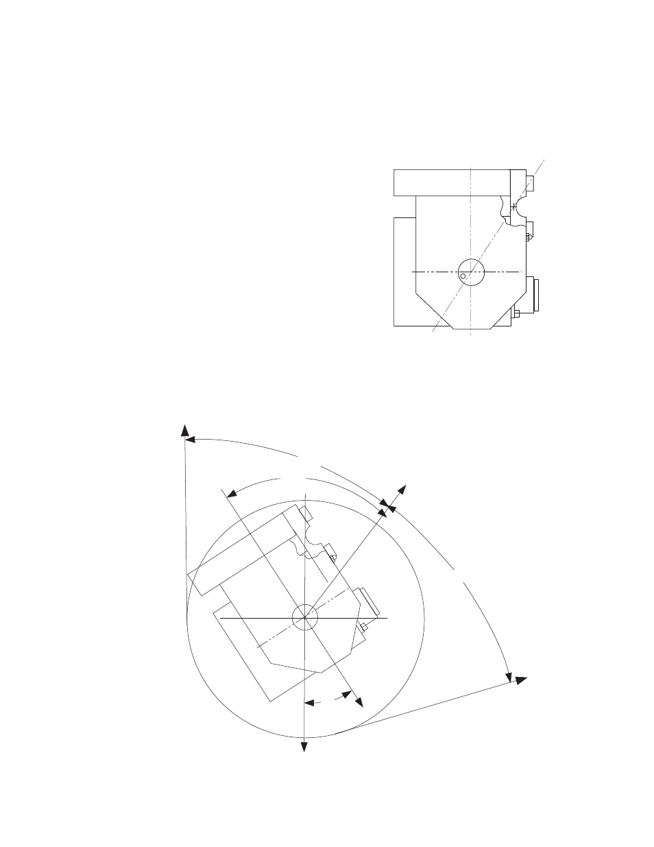
E. Description of Operation
The total resultant load per cell (RF) is calculat-
ed by resolving all force vectors acting upon the
Tensioncell, with respect to the Loading Line
(OL). (RF) is the resultant of both TENSION and
TARE loads, PER CELL!! (See Figure 5)
The intrinsic design of Warner Electric
Tensioncells allows the location of the Resultant
Load of Strip Tension (H) on any angle with
respect to the Load Line (OL). Note, however,
that the Total Force vector (RF) must always be
calculated on the line (OL).
Any force vector falling on the line (OR) (through
the pivot point of the C-Flexure) will produce no
deflection, and thus no electrical output.
Rotating the Tensioncell on its mounting bolt
changes the force vectors on the cell. This fea-
ture makes it possible to minimize the tare com-
ponent and maximize the load signal output.
Nominal
L
R
Figure 5
Figure 6
E
D
H
E
RF
N
TW
T
T
The resultant tare is minimized by mounting the
Tensioncell so that (N) is 31°. (See Figure 6)
- UNIBRAKE NEMA 4 (6 pages)
- UNIBRAKE (8 pages)
- ARC 2000 (16 pages)
- ARC Clutch_ZRC Top Load (18 pages)
- ZRC Clutch_ARC Top Load (18 pages)
- Dairy Cap Chuck (24 pages)
- Dairy Capping Headsets (10 pages)
- Autogap 475 & 650 (4 pages)
- Brushholder Installation (2 pages)
- Autogap 825-1225 (2 pages)
- Electro-Packs EP-170, 250, 400, 500, 825, 1000, 1525 (20 pages)
- Electro-Brake 375, 475, 650, 825, 1000, 1225 (20 pages)
- Electro-Clutch EC-375, EC-475, EC-650, EC-825, EC-1000, EC-1225 (20 pages)
- 5300-101-001 Collector Ring (2 pages)
- 5301-101-010 Collector Ring (2 pages)
- Brushholder Assembly and Mounting Dimensions (2 pages)
- SF_PB 400 (2 pages)
- SF_PB 250 (2 pages)
- Autogap 825-1525 (4 pages)
- Electro-Module EM-50, EM-100, EM-180, EM-210, EM-215 (22 pages)
- FB-375, 475, 650 (14 pages)
- 5200-101-012 Conduit Box Kit (4 pages)
- 5200-101-011 Conduit Box Kit (4 pages)
- 5200-101-010 Conduit Box Kit (4 pages)
- Recommended Electrical Installation Procedure for Warner Electric Clutches and Brakes (2 pages)
- EP-400 Vertical Mounting (2 pages)
- EP-250 Vertical Mounting (2 pages)
- Autogap 500 (4 pages)
- ER 825 and 1225 Normal Duty (16 pages)
- ER 825 and 1225 Heavy Duty (14 pages)
- ERS Electrically Released Brakes (6 pages)
- AT Brakes & Clutches Complete Brake Repair – On the Shaft, Sizes 25, 55, 115 (4 pages)
- AT Brakes (6 pages)
- AT Brake–Major Service Repair Instructions for Sizes 25, 55, 115 (9 pages)
- AT Clutch – Major Service Sizes 25, 55, 115 (12 pages)
- 5162-101-002 Conduit Box Kit (6 pages)
- Electrically Released Permanent Magnet Clutch Compatible Modules (4 pages)
- Electrically Released Motor Brake Module for EM-MBFB and EUM-MBFB (6 pages)
- Electrically Released Brake Module For EM-FBB and EUM-FBB (4 pages)
- Electrically Released Brake ER-375, ER-475, ER-650 (12 pages)
- Autogap 825-1525 Special Heavy Duty (4 pages)
- 5370-101-042 Conduit Box Kit (4 pages)
- Preassembled Clutch_Electrically Released Brake Module (7 pages)
- EUM-50_EUM-100_EUM-180_EUM-210_EUM-215 (16 pages)
- 5370-101-045 Conduit Box Kit (5 pages)