Specifications, Electrical zero adjustment, Mechanical alignment – Warner Electric FM Series Foot Mounted Load Cells AC10 Measuring System A-B-C30 User Manual
Page 55: Electrical installation
55
Warner Electric • 800-825-9050
P-2012-5
Specifications
Type "K" 24 volt DC LVDT Specifications
Input . . . . . . . . . . . . . . . . . . . . . . . . .6-30 volts DC
Output . . .0.5-6.5 volts DC (nominal, open circuit)
Output Impedence . . . . . . . . . . . . . . . .2.5K ohms
Current Consumption . . . . . . . . . . . . . . . . .40 mA
Recommended Load . . . . .100K ohms or greater
Max. Operating Temp . . . . . . . . . . . . . . . . . .250°F
Note: Warner Electric loadcells are
calibrated for 24 volt DC input voltage to
provide a 0.5 to 6.5 volts DC output signal.
Electrical Zero Adjustment
(Read the complete Electrical Zero Adjustment
procedure before proceeding with the adjust-
ment.)
1. Disengage strip from the measuring roll so
that no tension force is applied to the load-
cell.
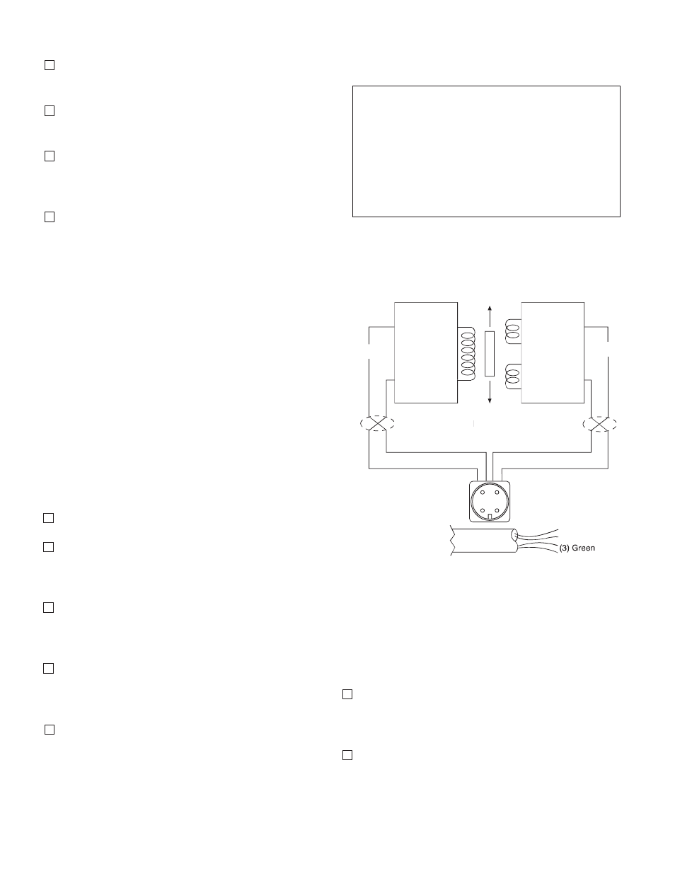
2. Connect a voltmeter to Pins C and D (See
Figure 9)
8. Position the roll with the Tensioncells on the
machine and fasten with the mounting bolts.
9. Rotate the Tensioncells to the proper mount-
ing angle and tighten the mounting bolts.
10. Lock the locating pad for each Tensioncell
against the machine frame using the 1/4-20
x 1/2 socket head capscrew.
11. Tighten the shaft in the mounting block on
the W1 unit. (The shaft end at W2 is left free
to allow it to move as the shaft expands with
temperature changes).
Black - (2)
Red + (1)
Green (3)
Blue (4)
Input
Output
X Twisted Leads
T
A B
A
Oscillator
Demodulator
P1
S1
S2
X
X
When Supplied
with Cable
(1) Red + DC
(2) Black – DC
–
– Signal
–
(4) White + Signal
C D
B
A
C
D
Figure 9
Mechanical Alignment
Align the sectional measuring roll to avoid any
mechanical binding or friction. The measuring
roll must be level and perpendicular to the path
of the strip material for accurate measurement.
The Mechanical Stops are fixed for the required
travel of the Load Table.
Electrical Installation
(Read the entire electrical wiring procedure
before proceeding.)
1. Turn off all electrical power to the loadcell.
2. Use twisted four conductor signal cable,
Belden 9402 or equivalent, in grounded steel
conduit from the LVDTs to the control panel.
3. Observing correct polarity, connect the posi-
tive (+) input lead to Pin A and the negative
(-) input lead to Pin B. (See Figure 9)
4. Connect the positive (+) output lead to Pin D
and the negative (-) output lead to Pin C.
(See Figure 9)
5. Repeat Steps 1 through 4 of the electrical
wiring procedure for the Tensioncells mount-
ed on the other end of the measuring roll.