Warner Electric Electro-Packs EP-170, 250, 400, 500, 825, 1000, 1525 User Manual
Page 5
5
Warner Electric • 800-825-9050
P-212 • 819-0078
Warner Electric • 800-825-9050
P-212 • 819-0078
9. Proceed as follows for EP-825-1525:
a. Slide the rotor and rotor hub assembly
with taperlock bushing over the shaft.
b. Remove the rotor hub from the worn rotor
by unscrewing the capscrews and install
the hub and bushing on the new rotor.
c. Remove any burrs, chips, dirt, or other
foreign material from the field, rotor
assembly, and shaft.
d. Slide the new rotor assembly onto its
shaft the same way it was removed. Note
the line scribed on the O.D. of the field to
help maintain the correct axial clearance
between the rotor and field. Tighten the
bushing to secure the assembly in place
on the shaft.
10. Reassemble the end bell in the
Electro-Pack unit. Reassemble the
capscrews and washers to the unit.
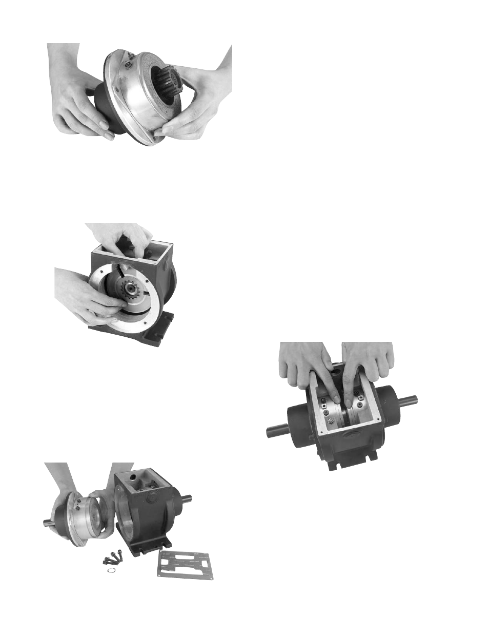
11. Set the autogaps by pressing each
armature into contact with its mating
component (either the magnet or rotor)
and then releasing it. (Figure 6)
12. Reconnect the electrical wires to the
magnet.
13. Reassemble the cover to the unit.
6. Assemble new armature on the armature hub
with the segmented side toward the magnet.
7. Assemble the second armature in the
opposite direction of the first. (Figure 4)
8. Proceed as follows for EP-170 through 500
(go to instruction 9 for EP-825 through 1525):
a. Remove the retainer ring holding the rotor
on the output shaft.
b. Remove the rotor and replace it with a
new one. Replace the retainer ring.
(Figure 5)
Figure 4
Figure 5
Figure 6
Figure 3