Warner Electric Electro-Packs EP-170, 250, 400, 500, 825, 1000, 1525 User Manual
Page 4
4
Warner Electric • 800-825-9050
P-212 • 819-0078
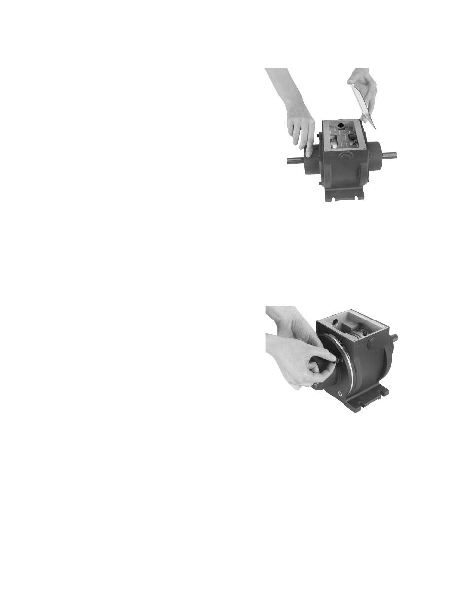
1. Remove the cover from the Electro-Pack unit.
(Figure 1)
2. Disconnect the wires from the magnet
terminals or disconnect the lead wires
(EP-170).
3. Remove the capscrews and washers from the
output end bell and remove the end bell.
(Figure 2)
4. Remove and discard the worn armature(s).
5. Remove the used magnet and discard it.
Assemble the new magnet to the end bell.
(Figure 3)
Electro-Packs
The Electro-Pack is a pre-assembled
clutch/brake package complete with input
and output shafts. These units are ready to
be installed in all standard power transmission
systems—V-belts and pulleys, chain and
sprockets, in-line couplings, timing belt drives,
and gear trains.
A. Installing the Electro-Packs
1. Provide a mounting surface for the
Electro-Pack that is rigid and flat with
the following tolerances.
Electro-Pack
Mounting Surface to be
Sizes
Flat in One Plane Within:
170
.004"
250
.004"
400
.004"
500
.010"
825
.010"
1000
.010"
1525
.010"
2. Connect the Electro-Pack into the drive
system. The input shaft is identified on the
unit. Use care when connecting the units!
Serious problems will occur if the power input
is connected to the output shaft.
Dimensions for the input and output shafts
are shown on the illustration drawings,
beginning on page 9.
3. Make the proper electrical connections
between the Electro-Pack and a suitable DC
power supply. Lead wires or terminals are
provided on the clutch and brake for this
purpose. A wiring diagram showing the
proper connections is furnished with each
Warner Electric power supply.
B. Replacing Worn Parts
The normal wearing components of an
Electro-Pack are the magnet, two armatures,
and rotor. The mating components (magnet
and armature or rotor and armature) generally
wear at the same rate and should be replaced
together.
Figure 1
Figure 2