Vanguard EZCT-2000B User Manual
Page 112
EZCT-2000B USER’S MANUAL
REV 1
108
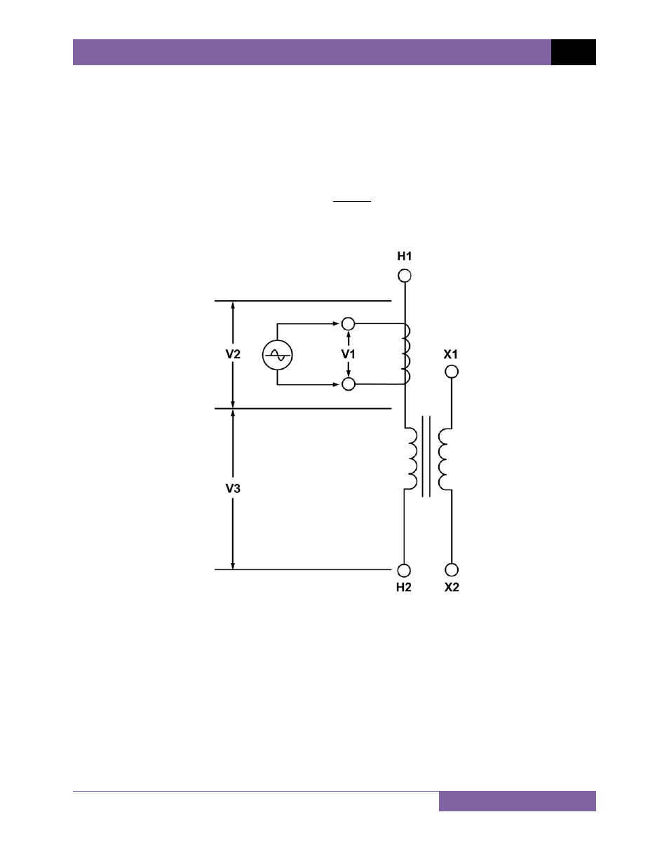
Figure 25 shows a typical connection of a CT mounted on the primary bushing of a single phase
transformer. When the voltage V1 is introduced to the CT's secondary winding, there is an
induced voltage (V3) on the primary winding of this single phase transformer. Since the only
access to the transformer is between terminals H1-H0, The V3 voltage will be included and the
turns-ratio will be:
Ratio=
(
)
Figure 25
Ideally, we would like to eliminate the V3 voltage and only see the V2 voltage. If the induced V3
voltage on the transformer winding cannot be eliminated, the turns-ratio measured will be
wrong!
See also other documents in the category Vanguard Accessories for electrical:
- Resistor Transducer Adapter 9095-UC (7 pages)
- Accu-Ohm 200 S2 (4 pages)
- Accu-Trans (28 pages)
- ATO-400 (43 pages)
- ATO-400P (44 pages)
- Auto-Ohm (22 pages)
- Auto-Ohm 100_200 s2 (31 pages)
- Auto‐Ohm 200 S3 (66 pages)
- DMOM-100 (35 pages)
- DMOM-100_200 s2 (42 pages)
- DMOM-200 (33 pages)
- Herculito (17 pages)
- ATRT-01 S2 (59 pages)
- ATRT-01_01B S3 (88 pages)
- ATRT-01_01B_01D (31 pages)
- ATRT-03_03A (114 pages)
- ATRT-03_03A S2 (147 pages)
- CVT-765 (46 pages)
- Tri-Phase (155 pages)
- CBCT (14 pages)
- CBPS-300 (16 pages)
- CT-3500 (24 pages)
- CT-3500 S2 (53 pages)
- CT-6500 (69 pages)
- CT-6500 S2 (82 pages)
- CT-7000 (83 pages)
- CT-7000 S2 (108 pages)
- CT-7000 S3 (137 pages)
- CT-7500 (76 pages)
- CT-7500 S2 (110 pages)
- CT-8000 (120 pages)
- CT-8000 S3 (145 pages)
- DigiTMR (86 pages)
- DigiTMR S2 (123 pages)
- DigiTMR S2 PC (31 pages)
- MCCB-250 (17 pages)
- UPS S2 (13 pages)
- EZCT-2000 (68 pages)
- EZCT-2000 (45 pages)
- EZCT-2000A (103 pages)
- EZCT-2000C Plus (119 pages)
- EZCT-S2 (66 pages)
- EZCT-S2A (98 pages)
- IRM-5000P (58 pages)