Vanguard DMOM-100_200 s2 User Manual
Page 17
DMOM-100/200 Series 2 Operating Procedures
17
Rev 2, 2009
6.0 CABLE CONNECTION
The DMOM is supplied with two 30-foot test cables with heavy-duty alligator clamps. Both
current (#1 AWG) and sense leads are combined into one cable (Figure 1.0). A typical cable
connection for the DMOM to a device under test (using the combined test lead) is shown in
Figure 9.0 and Figure 11.0. Figure 8.0 and Figure 10.0 illustrate the connection using separate
current and sense leads.
To protect the DMOM against static discharge in the substation, always connect the unit’s
ground stud to the substation ground. It is also highly recommended that one side of the circuit
breaker bushing be grounded during testing to eliminate any static discharge through the
DMOM.
NOTE
The sense input is not polarity sensitive. The sense cables may be
connected to either input without affecting the DMOM reading accuracy.
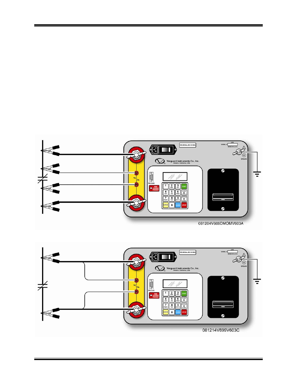
Figure 8.0 DMOM-100/200 Connection Diagram 1 (Separate Leads)
Figure 9.0 DMOM-100/200 Connection Diagram 2 (Combined Leads)