Xsel-r/s/rx/sx/rxd/sxd 22 – IAI America XSEL-S User Manual
Page 28
3. XSEL-R/S/RX/SX/RXD/SXD
22
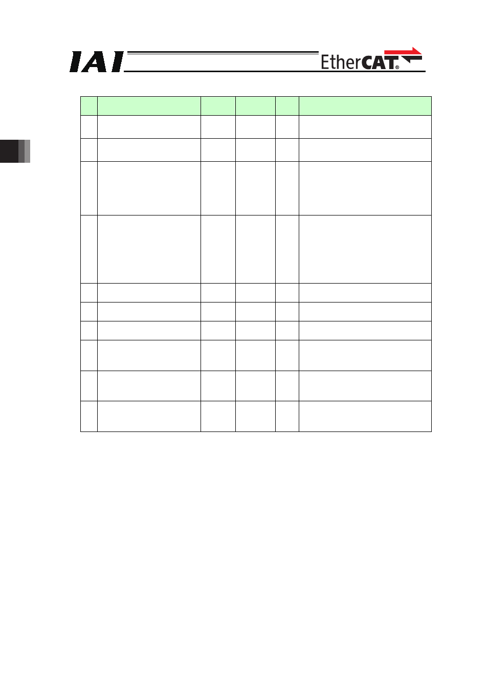
No.
Parameter name
Default
(reference) Input Range Unit
Remarks
17 Network I/F Module 1
Fix-Allocated Output Port Start No.
4000
-1 to 6999
4000
300+(Multiples of 8)(300 to 599)
4000+(Multiples of 8)(4000 to 6999)
[Unavailable when it is negative figure]
18 Network I/F Module 1
Error Monitor
1
0 to 5
1
0:
No Monitoring (Not to use Network I/F
Module 1)
1:
Monitoring
120 Network Attribute 1
640001
H
0 to
FFFFFFFF
H
Opti-
onal
Bit 16 to 23:
Value of Link Timeout at initializing
(Example) Default 64
H
= 10sec
Bit 28 to 31: Network I/F Module 1
Input port data select for link
error
(0: Clear, 1: Hold)
225 Network I/F Module Control
*6
00
H
to 37
H
06
Bit 0 to 3:
Type of Network I/F Module Control 1
6: EtherCAT
Bit 4 to 7:
Type of Network I/F Module Control 2
0: Not Mounted
1: CC-Link
2: DeviceNet
3: PROFIBUS
226 Network I/F Module 1
Node Addres
17
0 to 65535
Opti-
onal
EtherCAT: 0 to 65535
(Make setting from master)
231 Network I/F Module 2
Remote Input Ports
0
0 to 256
0
8 port unit
232 Network I/F Module 2
Remote Output Ports
0
0 to 256
0
8 port unit
233 Network I/F Module 2
Extension Input Port Start No.
-1
-1 to 299
1000 to
3999
-1
0+(Multiples of 8)
or
1000+(Multiples of 8)
[Ineffective when -1 is selected]
234 Network I/F Module 2
Extension Output Port Start No.
-1
-1
300 to 599
4000 to
6999
-1
300+(Multiples of 8)
or
4000+(Multiples of 8)
[Ineffective when -1 is selected]
235 Network I/F Module 2
Error Monitoring
1
0 to 5
0
0: No Monitoring
(Not to monitor condition of link to PLC
(master))
1: Monitoring