Ix-nnw60, 71 7. specifi cations – IAI America IX-NNW8040 User Manual
Page 77
71
7. Specifi
cations
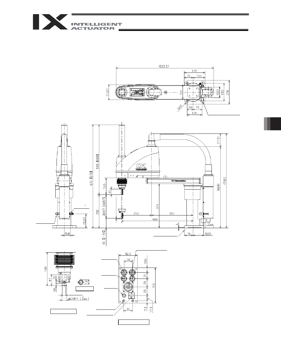
IX-NNW60
4 -
I11 hole
I24 counterbore, depth 5
5 (
M
echa
ni
cal
e
nd)
I6 quick
air-tube joint
I4 quick
air-tube joint
ALM (*2)
BK SW
Brake-release switch
Spacer
Outer diameter
I7
Height 10 (M4)
Depth 5 (*1)
Detailed view of panel
I14, hollow
Section A-A
Reference surface
Red
Yellow
Black
White
Purge air inlet
Outer diameter
I6 (inner
diameter
I4)
Intake/exhaust
port (*3)
Detailed view of tip
User connector (23-pin
connector for user wiring)
*1: External force applied to the spacers must not exceed 30 N
in the axial direction or 2 N
m in the rotating direction (for
each spacer).
*2: The LED operates only when the user provides a circuit that
receives controller I/O output signal and supplies 24 VDC to
the LED terminal in the user connector.
*3: Insert a tube with an outer diameter of
I12 into the
intake/exhaust port, and extend the tube to a location where
it will not come in contact with water.