Warning – IAI America IX-NNW8040 User Manual
Page 35
29
5. Precautions for Use
The robot comes with a D-sub 25-pin mating plug for the user connector.
Solder a user-supplied cable to the D-sub connector (plug), attach the supplied hood, and then connect to
the user connector (socket). Use a shielded cable with an outer diameter of
I11 or less.
To turn on the indicator, the user must configure a dedicated circuit that uses the controller I/O output signal,
etc.
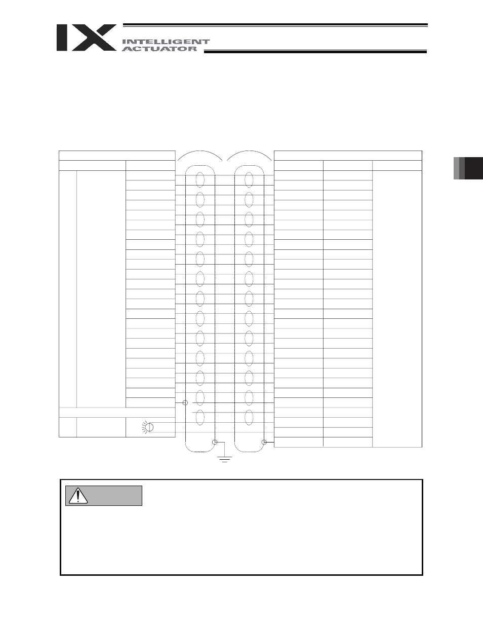
User connector pins and corresponding Y-terminals
z Before commencing wiring/piping work, turn off the power to the controller and the power/air
supplies to the robot. Failure to do so may cause the robot to malfunction.
z Use cables and tubes within their specifications. Failure to do so may result in fire or short circuit
due to an overheated cable, or may cause air leaks.
z Connect the shielded cable to the hood. Otherwise, the robot may malfunction due to noise.
z In the case of the dust-proof/splash-proof specification, Y-terminals U24 and U25 cannot be used.
To base
Inside unit
Cable
Arm 2 side
Connection
Waterproof
connector,
24 pins
Indicator
(LED)
Controller side
Y-terminal designation
Wire color
Orange 1 red
Light gray 1 red
Connection
Y-terminal
Orange 1 black
Light gray 1 black
White 1 red
White 1 black
Yellow 1 red
Yellow 1 black
Pink 1 red
Pink 1 black
Orange 2 red
Orange 2 black
White 2 red
White 2 black
Yellow 2 red
Yellow 2 black
Pink 2 red
Pink 2 black
Orange 3 red
Orange 3 black
Light gray 2 red
Light gray 2 black
Light gray 3 red
Light gray 3 black
White 3 red
White 3 black
Yellow 3 red
Green
No.
1
2
3
4
5
6
7
8
9
10
11
12
13
14
15
16
17
18
19
20
21
22
23
24
25
U1
U2
U3
U4
U5
U6
U7
U8
U9
U10
U11
U12
U13
U14
U15
U16
U17
U18
U19
U20
U21
U22
U23
U24
U25
LED +24V
LED G24V
FG
User Connecto
r
ALM
Warning