4 user wiring and piping – IAI America IX-NNW8040 User Manual
Page 33
27
5. Precautions for Use
5.4
User Wiring and Piping
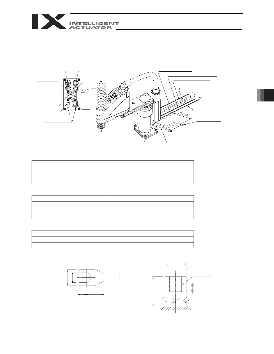
The robot comes with standard cables and tubes that the user can use in a desired wiring/piping
configuration.
User connector specifications
Rated voltage
3.0 V
Permissible current
1.1 A
Conductor size and number of wires
AWG 26 (0.15 mm
2
), 24 wires
Other
Twisted-pair cable (1 to 22), shielded
(Pin 24)
Piping specifications
Normal service pressure
0.8 MPa
I4 mm x I2.5 mm, 2 pieces
Dimensions (outer diameter x inner
diameter) and number of tubes
I6 mm x I4 mm, 2 pieces
Working medium
Air
ALM (indicator) specifications
Rated voltage
24 VDC
Rated current
12 mA
Illumination color
Red LED
Shape of Y-terminal
Spacer for user part installation
User connector,
waterproof, 24
pins (including the
shield terminal)
ALM indicator
Spacer for user
part installation
BK SW
Brake-release
switch
Standard cable (5 m)
BK power cable (outside robot)
M cable (outside robot)
PG cable (outside robot)
Y-terminal at the end
To controller
Air tube
I4 (black, white)
I6 (red, yellow)
I4, I6 quick joint
(2 pcs. each)
U cable
(outside robot)
M4, depth 5
30 N or less
External force applied to the spacers must not
exceed 30 N in the axial direction or 2 N
m in
the rotating direction (for each spacer).
2 N
m or less
I6 (red) quick
air-tube joint
5.2
3.2
2.6 5.9
I7
10
I4 (black) quick
air-tube joint
I6 (yellow) quick
air-tube joint
I4 (white) quick
air-tube joint
Purge air inlet on opposite side
(applicable tube: outer diameter
I6)