IAI America IX-NNW8040 User Manual
Page 16
10
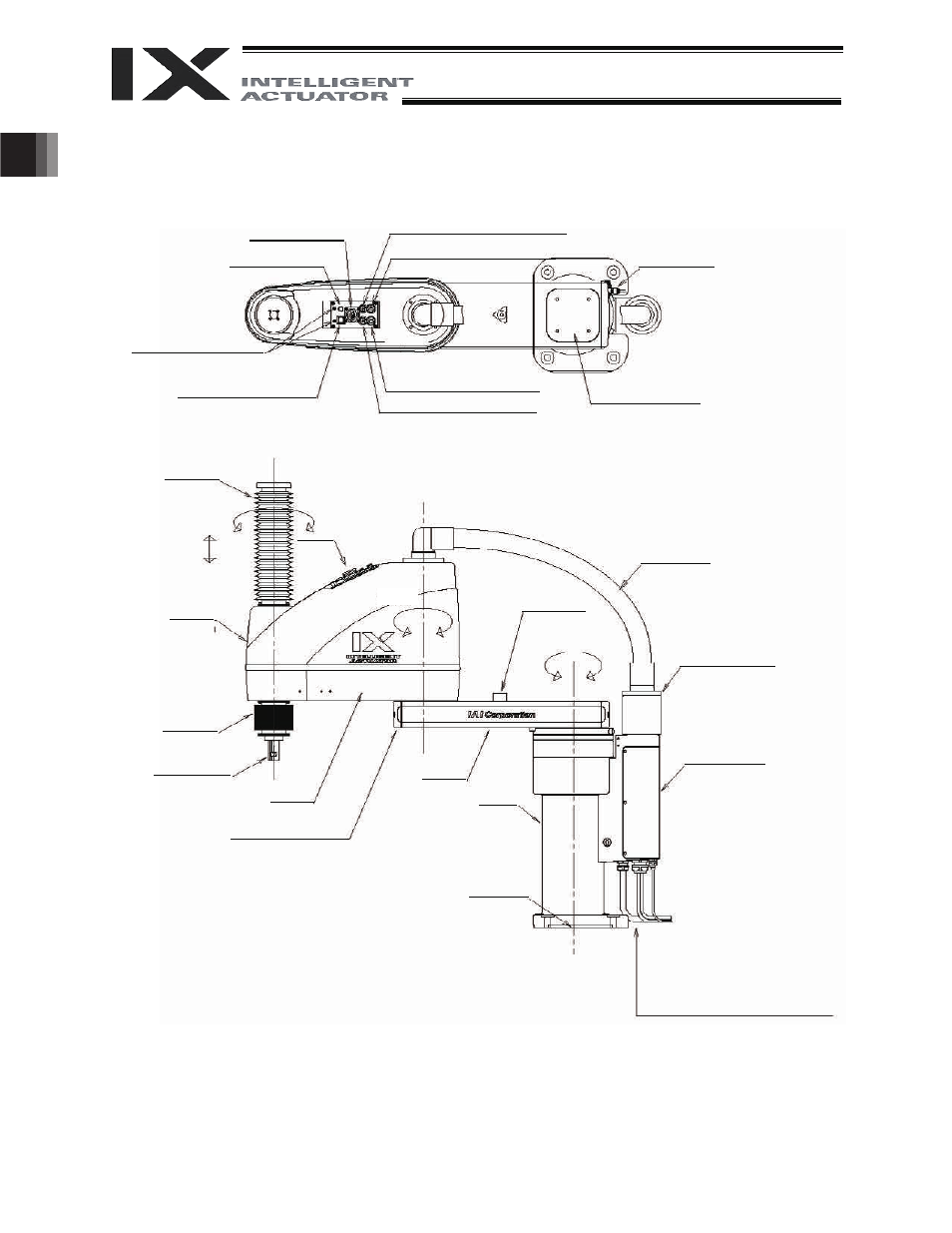
1. Names of Robot Parts
(2) IX-NNW70
/80
User connector
ALM (indicator)
I4 joint for user piping, black
I6 joint for user piping, red
Spacer for
user part installation
BK SW
(Brake-release switch)
I4 joint for user piping, white
I6 joint for user piping, yellow
Top cover (arm 1)
Axis 4
(rotational axis)
Panel
Ball screw
spline shaft
Cover
(arm 2)
Wiring duct
Axis 3
(vertical axis)
Axis 2
Arm 2
End cover (arm 1)
Arm 1
Base
Cover (base)
Mechanical stopper
for arm 1/arm 2
Axis 1
Mechanical
stopper for
arm 2
Reference
surface
M cable (outside robot)
PG cable (outside robot)
U cable (outside robot)
BK power cable (outside robot)
Air tubes (
I4: 2 pcs., I6: 2 pcs.)
Bellows
Suction joint
Bellows
This manual is related to the following products: