IAI America RCLE-GR5L User Manual
Page 33
27
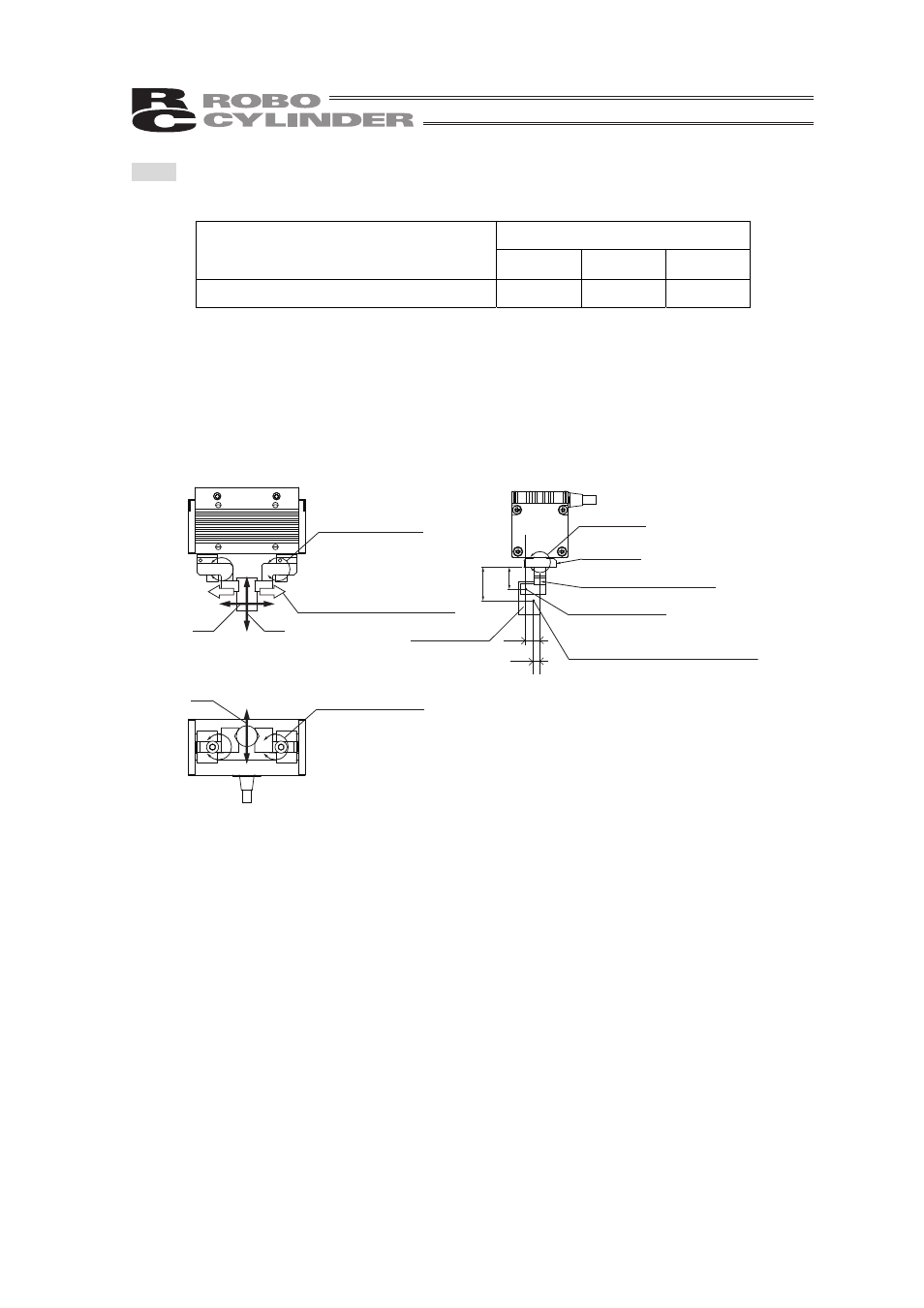
Step 2: Check the allowable vertical load of the fingers and allowable moment
Table 1. Allowable load and allowable moment on the fingers
Allowable Load Moment [Nm]
Allowable load in the vertical direction [N]
F
zmax
M
amax
M
bmax
M
cmax
12 0.02
0.02
0.04
Check the vertical load and the load moments applied to the fingers. Do not exceed the
allowable range of F
z
, M
a
, M
b
and M
c
.
The values shown are the static allowable load and static allowable load moments that
may be applied to each finger. Also, the allowable moment is the value the load is applied
only in one direction. If the load is applied in two directions, divide the specified values in
half.
F
X
F
Z
F
Y
L
C
L
G
H
C
H
G
M
a
= M
la
+ M
oa
M
la
, M
oa
M
b
= M
lb
+ M
ob
M
lb
, M
ob
M
a
= M
oc
Finger
Finger Attachment
Work Part
Reaction force
against work part hold
Center of gravity for finger
attachment and work part
Holding Point
F
X
: External force in X direction applied to finger attachment [N]
F
Y
: External force in Y direction applied to finger attachment [N]
F
Z
: External force in Z direction applied to finger attachment [N]
L
G
: Distance from finger attachment surface to holding point
(holding point) [m]
H
G
: Distance from finger center to holding point (overhang) [m]
L
C
: Distance from finger attachment surface to center of finger
attachment gravity [m]
H
C
: Distance from finger center to center of finger attachment
gravity [m]
Mla : Moment in Ma direction generated on fingers by holding
force [Nm]
Mlb : Moment in Mb direction generated on fingers by holding
force [Nm]
MOa : Moment in Ma direction generated on fingers by external
force [Nm]
MOb : Moment in Mb direction generated on fingers by external
force [Nm]
MOc : Moment in Mc direction generated on fingers by external
force [Nm]
Ma : All the moments in Ma direction generated on fingers [Nm]
Mb : All the moments in Mb direction generated on fingers [Nm]
Mc : All the moments in Mc direction generated on fingers [Nm]