2 heat release effect by heat sink application – IAI America RCLE-GR5L User Manual
Page 26
20
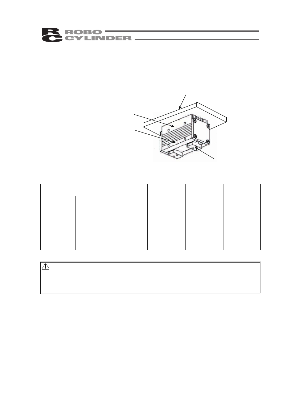
6.4.2 Heat Release Effect by Heat Sink Application
The graph below shows the temperature rise (maximum value) from the ambient temperature when
the unit is operated with 50% duty with 2 types of heat sinks applied on the attachment surface (top
surface).
Finger
Attachment Surface
(Upper side on side surface)
Attachment Surface
(Lower side on side surface)
Heat Sink
Reference data : Temperature Rise from Ambient Temperature (Maximum Value)
Ambient temperature at measurement : Approx. 25
qC
Heat Sink
Dimensions Material
Heat Sink
Attachment
Surface
(Upper side on
side surface)
Attachment
Surface
(Lower side on
side surface)
Finger
60
u 60 u 5
Aluminum
Anodized
Surface
Approx. 22
qC
Approx. 26
qC
Approx. 25
qC Approx.
36
qC
150
u 85 u 10
Aluminum
Polished
surface
Approx. 17
qC
Approx. 23
qC
Approx. 22
qC Approx.
34
qC
Note : Even if a heat sink is attached on the top of the unit, the temperature on the fingers
would not decrease much. To block heat from being conducted to the work part, use a
material with low heat conductivity such as polyacetal for the finger attachments. The
heat of the unit is conducted from the fingers to the work part via the finger
attachments.