Driving circuit – IAI America RCLE-GR5L User Manual
Page 27
21
7. Driving Circuit
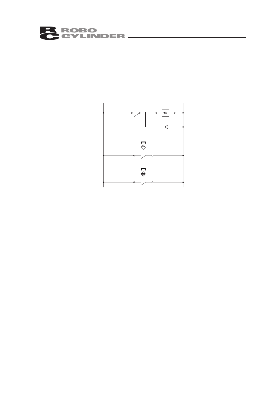
Follow the example of the driver circuit shown below to apply the diode, relay and circuit protector
(or fuse) to the cable ends and connect to the 24V DC power supply. To protect the gripper, make
sure to apply the circuit protector (or fuse). Please prepare the diode, relay and circuit protector (or
fuse) separately from the product.
The cable length should be approximately 1m. It is bare wire on one end.
24V
0V
Relay
Chuck
WT
BK
Chuck-Open Detection Switch
BR
BL
Chuck-Close Detection Switch
BR
BL
Circuit
Protector
or Fuse
(1) Selection of the Circuit Protector or Fuse
Select ones with the following performance:
Ɣ Rated Current
: 2A
Ɣ Transient Characteristics : Should cut the power within 3sec at 200% of rated current
Select from a high-speed type or a transient type if a circuit
protector is used.
(2) Relay
Select ones that satisfy the following conditions:
Ɣ Select solid state relays when open and close operation is frequently conducted.
Ɣ Output rated load voltage : 24V DC
r10%
Ɣ Output load current
: 1A or less
(Reference) G3FD-X102SN DC5-24 manufactured by OMRON is available.
(3) Diode
Counter EMF is generated when turning the power OFF from being ON to close the fingers of
the gripper from being open. Select a diode that is able to cut the voltage caused by the
counter EMF.
Ɣ Counter electromotive voltage : Approx. 40V
Ɣ Counter electromotive current : Approx. 0.1A
(Reference) D1N60 manufactured by Shindengen Electric Manufacturing is available.