A. control overview, B. menu structure, C. navigation of the display – HTP ELP-199 User Manual
Page 54
54
LP-294 REV. 2.20.14
A. CONTROL OVERVIEW
The control is one of the primary safety devices of the boiler. It monitors the boiler safety sensors to assure safe and efficient operation,
and has the capability to lock out and halt boiler operation when a fault or error is detected.
Also, the control has many features associated with hydronic design. By properly customizing boiler operating parameters, the installer
can provide safe, efficient heating and domestic hot water to the end user.
B. MENU STRUCTURE
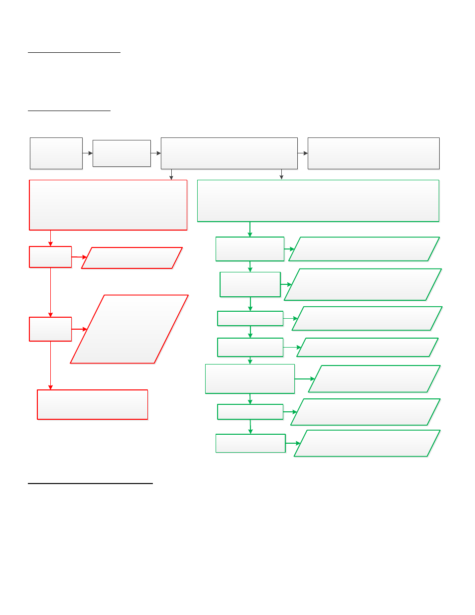
After the display has established communication with the main board, the installer will be able to use the display to navigate through the
boiler menu structure. That structure is summarized in Figure 29.
POWER ON
TO BOILER
INITIALIZING
SCREENS
BOILER MAIN SCREEN
(SHOWS CURRENT STATUS OF THE BOILER)
See Part 11, This Manual
CASCADE MAIN SCREEN
(VISIBLE ONLY IN CASCADED SYSTEMS)
See Part 11, This Manual
USER MENU
(ALLOWS USER TO VIEW CURRENT BOILER
STATUS AND CHANGE SETTINGS)
PRESS THE RIGHT ARROW KEY ON THE DISPLAY AT THE MAIN
SCREEN TO VIEW THESE SCREENS
See Part 12, This Manual
BOILER
STATUS
BOILER
SETTINGS
CASCADE STATUS
(VISIBLE ONLY IF BOILER IS
INSTALLED IN A CASCADED SYSTEM)
DISPLAYS CURRENT
BOILER DATA
ALLOWS USER TO
CHANGE CH
SETPOINT, AND/
OR TEMPERATURE
FROM
FAHRENHEIT TO
CELCIUS
INSTALLER MENU
(ALLOWS INSTALLER TO CHANGE AND VIEW CURRENT BOILER SETTINGS)
AT THE MAIN SCREEN, PRESS AND HOLD THE ENTER KEY. WHILE HOLDING, PRESS AND HOLD THE
RIGHT ARROW KEY FOR 3 SECONDS, OR UNTIL THE INSTALLER MENU IS INITIATED.
See Part 13, This Manual
BOILER STATUS
INSTALLER
BOILER
CONFIGURATION
CH SETTINGS
VIEW CURRENT BOILER STATUS
AND/OR CHANGE SETTINGS
ALLOWS INSTALLER TO CHANGE
BOILER INPUTS AND OUTPUTS
FOR A CUSTOM INSTALLATION
DHW SETTINGS
CASCADE SETTINGS
(VISIBLE ONLY IF BOILER IS
INSTALLED IN A CASCADED SYSTEM)
SYSTEM TEST
LAMBDACONSTANT
ALLOWS INSTALLER TO ADAPT
CH SETTINGS TO INSTALLATION
ALLOWS INSTALLER TO SET
DHW SETTINGS
ALLOWS INSTALLER TO
CUSTOMIZE THE CASCADE
SYSTEM
ALLOWS INSTALLER TO RUN
DIAGNOSTIC TESTS ON THE
BOILER SYSTEM
ALLOWS INSTALLER TO
MODIFY COMBUSTION
SETTINGS
Figure 29
– Menu Structure
C. NAVIGATION OF THE DISPLAY
The control features a four line LCD display to provide informative messages about the operation of the boiler. Six navigation and
operation keys allow the user/installer to view and adjust many boiler operating parameters. Two LED lights inform and alert the
user/installer to Cascade status and possible operating issues.
The following describes how to navigate control parameters using the display.