M. cascade master and follower wiring – HTP ELP-199 User Manual
Page 47
47
LP-294 REV. 2.20.14
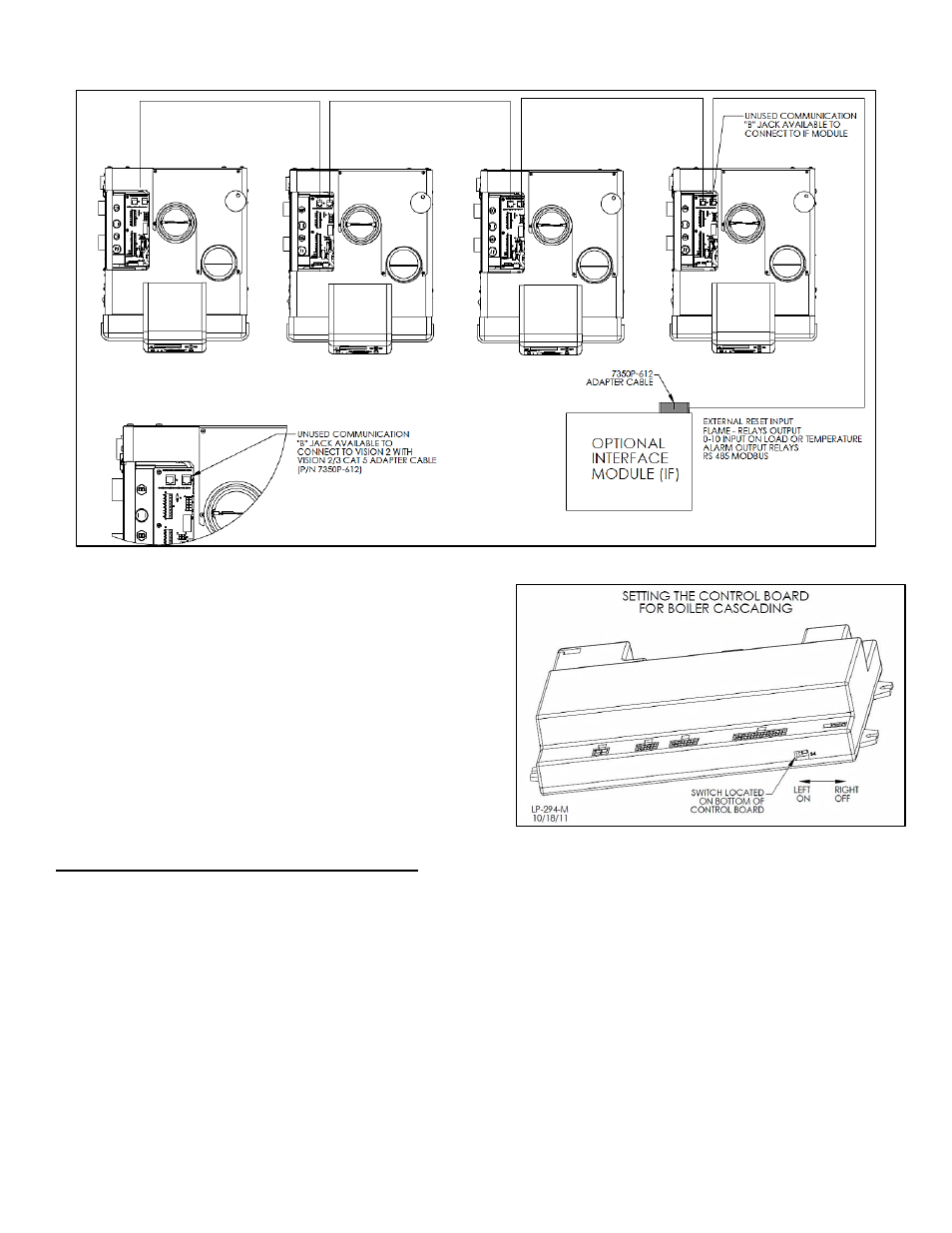
Figure 25
– Daisy Chain Wiring Configuration, with Optional Interface Module – LP-294-L
3. Route the communication cables through one of the knockouts in the
cabinet.
4. Connect the boilers in a daisy chain configuration as shown below. It
is best to wire the boilers using the shortest wire runs rather than trying
to wire them in the order they are addressed. The communication bus
jacks on the customer connection panel are interchangeable so you
can use either one or both in any order to connect the cable. If you
have connected the boilers to each other properly, two of the boilers will
have one open connection port on them.
5. It is important to set the bus master switch on the control board to the
ON (left) position on the master boiler, and to be sure that the switch is
set to OFF (right) on the follower boilers and the Interface Module (if
used) so there will be no adverse operation of the communication bus.
The factory default position is ON.
M. CASCADE MASTER AND FOLLOWER WIRING
1. Wiring for the Cascade Master is accomplished in the same way as a single boiler, with one exception: The bus communication
switch must be flipped to the ON (left) position on the Master. See Figure 26. Connect the system pump hot wire to the terminal marked
SYS PUMP.
2. The Follower is wired in the same way as the Master, with two notable exceptions:
a. Pumps and sensors are connected to the Cascade Master ONLY.
b. The bus communication switch on Follower boilers must be set to the OFF (right) position to prevent bus communication
interference.
NOTE: The cascaded system will not operate properly if the bus communication switches are set wrong.
Figure 26 - Setting the Control Board for Cascading