16 of 81 – Gilderfluke&Co BR-SmartMedia User Manual
Page 24
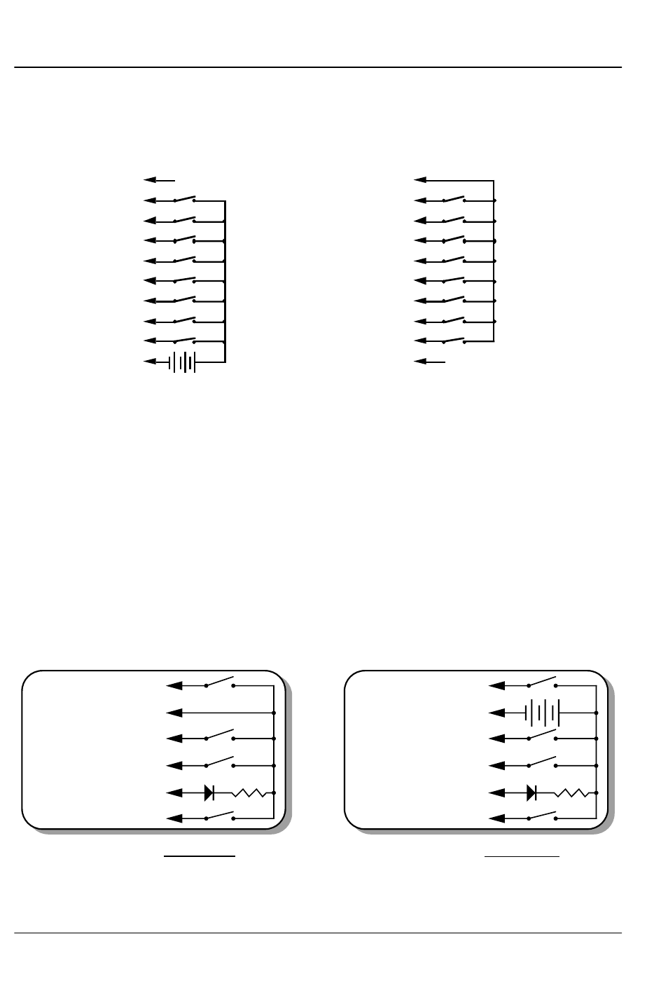
The 1/4 J6 Input is optically isolated. It can be set to run from
an external power source (default configuration) or the same
power as the Rack Smart Brick Brain. This is selected by moving
Switch 5 as shown on the board.
SUPPLY (not used)
+
(Brown) PIN #1
(red) PIN #2
(orange) PIN #3
(yellow) PIN #4
(green) PIN #5
(blue) PIN #6
(violet) PIN #7
(grey) PIN #8
(white) PIN #9
(black) PIN #10
GROUND (not used)
DATA BIT 7
DATA BIT 6
DATA BIT 5
DATA BIT 4
DATA BIT 3
DATA BIT 2
DATA BIT 1
DATA BIT 0
+ 5 to 24 VDC SUPPLY
GROUND
DATA BIT 7
DATA BIT 6
DATA BIT 5
DATA BIT 4
DATA BIT 3
DATA BIT 2
DATA BIT 1
DATA BIT 0
Internal Power
External Power
(Brown) PIN #1
(red) PIN #2
(orange) PIN #3
(yellow) PIN #4
(green) PIN #5
(blue) PIN #6
(violet) PIN #7
(grey) PIN #8
(white) PIN #9
(black) PIN #10
‘J8’ Inputs: If Switch #4 is in the ‘Dumb’ Brick position, the BR-
SmartMedia will be operating as a ‘Dumb’ Brick. The trigger inputs
and status output normally found on a ‘Dumb’ Brick are brought
out on the edge connector. When plugged into any Gilderfluke &
Co. Brick card cage, this will be brought out on a RJ-12 connec-
tor on the card cage. There should never be both ‘Smart’ and
‘Dumb’ Bricks in the same card cage. They share the same pins
on the edge connector and backplane. Damage may result if
both are installed in the same card cage.
There are four optically isolated digital inputs which can be
used to start, stop, pause or select specific show sequences to
play. Facing the end of the wire, with the latch upwards, the
pinout of a standard ‘J8’ cable is as follows.
+
+ 12 to 24 VDC SUPPLY
BLUE #6 (Input C')
YELLOW #5 (status out)
GREEN #4 (Input 'A')
RED #3 (Input 'B')
BLACK #2 (common)
WHITE #1 (Input 'D')
2.2K-4.7k
LED
2.2K-4.7k
LED
J8 with Sw8 set for INTERNAL power
J8 with Sw8 set for EXTERNAL power
BLUE #6 (Input 'C')
YELLOW #5 (status out)
GREEN #4 (Input 'A')
RED #3 (Input 'B')
BLACK #2 (common)
WHITE #1 (Input 'D')
Any event can be triggered on either the ‘closing’ or ‘opening’
edge of any input. A ‘closing’ is when you apply a voltage to an
G
ILDERFLUKE
& C
O
.• 205 S
OUTH
F
LOWER
S
TREET
• B
URBANK
, C
ALIFORNIA
91502 • 818/840-9484 • 800/776-5972 •
FAX
818/840-9485
E
AST
C
OAST
/F
LORIDA
O
FFICE
• 7041 G
RAND
N
ATIONAL
D
RIVE
• S
UITE
128d • O
RLANDO
, F
L
. 32819 • 407/354-5954 •
FAX
407/354-5955
16 of 81