Reese 30067 RAIL KIT User Manual
Page 7
CAUTION:
Check for obstructions before drilling. Failure to do so could result in damaged fuel or brake lines, structural
members, etc.
CEQUENT TOWING PRODUCTS
does its best to communicate tow vehicle manufacturer
changes; however, it is ultimately the responsibility of the installer to prevent damage due to installation.
8. Slide rail assembly as far rearward as possible then using frame bracket as template, and after checking rails are
square with each other, drill pilot holes in frame. Enlarge pilot holes to 21/32” diameter holes (
Figure 15
).
Optional: Spray under coating around drilled holes to prevent rusting.
7
30067IN –08DEC05C
PCN8405
©2005 CEQUENT TOWING PRODUCTS, INC.
Litho in USA
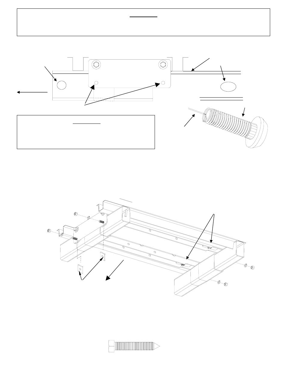
9. Thread 5/8” x 2” knurl bolt onto pull wire (
Figure 16
). Insert straight end of pull wire into access hole and guide
wire through drilled mounting holes. Pull wire out through mounting hole to position rib neck bolt for connecting rail
bracket and chassis rail (
Figure 17
). Repeat process for all four knurl bolt locations.
10. Loosely attach frame brackets to frame using 5/8” x 2” rib neck bolts, spacers, lock washers, and nuts; fasten until
hand tight (
Figure 17
).
11. Using pointed bolt (
Figure 18
), screw pointed bolt in to the nuts that are welded to the rail assembly until a prick
mark is visible in the truck bed (
Figure 17
). Access to the fourth welded nut is obstructed by chassis components;
the fourth prick mark must be measured from the other three prick marks (
Figure 19
). If you have a plastic bed
liner cut 19” X 4” slots in plastic drop-in bed liner measured from prick marks in truck bed. If the
Signature Series
slider
fifth wheel assembly is used, then see fifth wheel slider assembly instructions for slot cut dimensions.
Figure 18
CAUTION:
It is important that 21/32" drill be used for holes in chassis
frame as knurl bolts may break if too small a hole is used
and neck may not grip if too large a hole is used.
Pull wire
Figure 16
5/8” knurl bolt
Figure 17
Front of
vehicle
INSERT SPACERS ON BOTH DRIVER AND PASSENGER SIDE WITH
1500 & 2500 Light Duty: both spacers between bracket and frame
2500 Heavy Duty & 3500: front spacer outside of bracket, rear
spacer between bracket and frame
Thread pointed bolt to create
prick marks
Figure 15
Front of
vehicle
Access
Hole
Access
Holes
Drill Frame
Mounting Holes