Reese 30866 TITAN 16K FIFTH WHEEL User Manual
Page 4
30866IN-11SEP28D
PCN13221 ©2011 REESE PRODUCTS, INC
LITHO IN CHINA
ASSEMBLY INSTRUCTIONS
WARNING:
•Connection for trailer wiring should be in the side of the truck bed between the driver’s
seat and the wheel well for the back truck axle
•Installation of connection rearward of the wheel well may result in user placing body
between truck and trailer. WHENEVER POSSIBLE, AVOID PUTTING BODY UNDER TRAILER
OR BETWEEN TRUCK AND TRAILER!
•If you need to place any part of your body under trailer or between truck and trailer:
All trailer tires MUST be blocked in front and behind each tire AND
Trailer landing gear MUST be resting on firm ground AND
Truck MUST be stationary, in park, with emergency brake on!
WARNING
Base rails must be bolted through the floor of the pickup to the brackets that attach to
the truck frame. DO NOT INSTALL BY FASTENING TO THE FLOOR OF THE PICKUP BOX
ONLY. The floor alone is not strong enough to carry the loads imposed by the trailer.
Fig. 7
BASERAILS
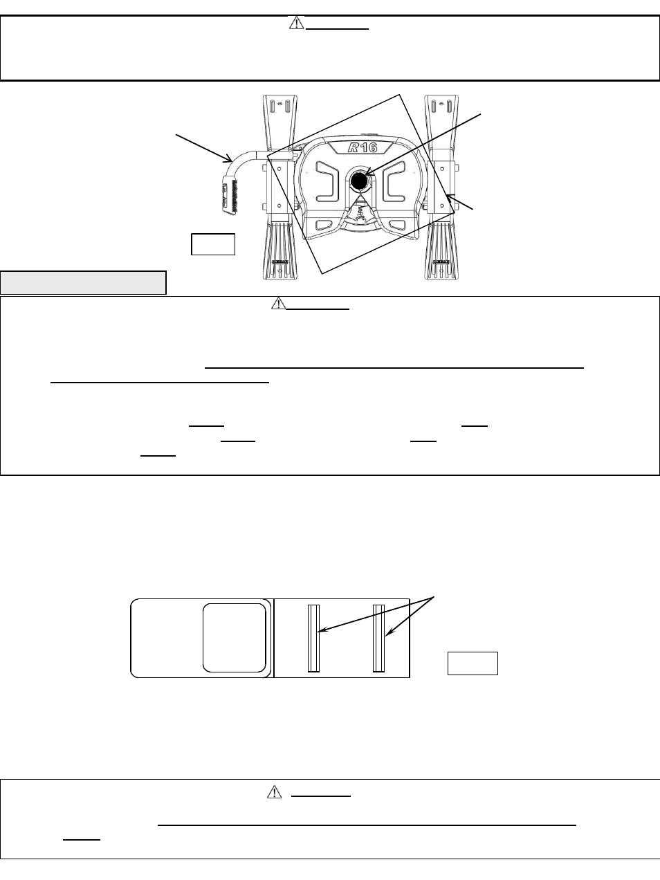
WARNING:
DO NOT use this hitch for towing a trailer with a pin box that could come in contact with or interfere with the
latch of the hitch handle when turning! (See Fig 6) If the pin box contacts the hitch handle or its latch when
turning, the trailer may become unhitched.
HANDLE
KING PIN
BOTTOM OF PIN BOX
Fig. 6
1.
Reference Fig. 20 on back page. Number in parentheses refer to parts in Fig. 20.
2.
R16 Fifth Wheel is contained in two cartons. Unpack and become familiar with parts on parts list. Base rail, brackets and
hardware are in separate kits with separate installation instructions for Fifth Wheel Rail Mounting Kit.
3.
Place two base rails across bed of truck (See Fig 7). Select one leg and place tabs through the middle rectangular slot in the
base rails. Slip long pull pins through holes in base rails from the inside out as shown so the cotter pins are on the outs ide of
the base rails. Repeat for other leg. Secure pull pins with the spring retaining pins .
4.
Select cross member (6) and install on leg aligning holes for hitch height desired. (Lowest position 14” highest 18”). Install four
½-
13x4.5” Socket Head bolts (8), with the heads towards the outside as shown, and lock nuts (9).
5.
Torque ½” nuts to 75 lb.ft.
6.
Install base rails and mounting brackets as described in “Installation Instructions for 5
th
Wheel Rail Mounting Kit.”