Fairbanks 2000 SERIES Rocker Column Railroad Scale User Manual
Page 27
03/10
27
50614 Rev. 5
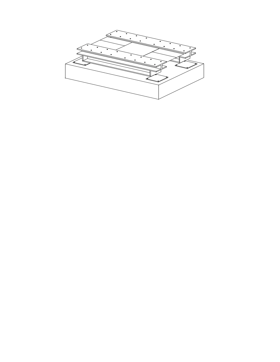
1
2
3
4
50614_30
Single modules are supported by two sections, or four load cells. A final grout plate elevation
adjustment should be made to match the mV/V outputs of the load cells to assure correct dis-
tribution of the scale's deadload among the four (4) points of support. Adjust the grout plate
leveling screws (equally) to match loadcells 1, 2, 3, and 4. When this has been completed,
ensure each loadcell grout plate is level to within .015" per foot.
NOTE: The loadcell numbering sequence shown is designed for interfacing Fairbanks INTA-
LOGIX technology instrumentation.
17: Perform a final check to all:
Loadcell grout plates are level to within .015" per foot.
All Load cells are vertical and plumb
Top flanges of the main beams are absolutely level and on the same plane as the end sec-
tions.
There is correct distribution of the scale's deadload among the loadcells.
All assembly hardware is secure and tight.
When complete, recheck to ensure all Grout Plates and Loadcells are plumb, square, and
level.
- 6001 Delta Series Analog Platforms (20 pages)
- NexWeigh (80 pages)
- 5001 Series QuickSilver IS (25 pages)
- 5000 Series Bench Scale Platforms (22 pages)
- Series II Bench Scales (14 pages)
- Series III Bench Scales (15 pages)
- SCB-R9000-B Series Ultegra Baggage (19 pages)
- SCB-R9000-14U Ultegra Bench Scale (16 pages)
- SCB-R9050 Series Ultegra MAX (17 pages)
- Ultegra Junior Bench Scale (18 pages)
- 1129 SERIES Dual Platform Counting Scale (50 pages)
- OMEGA SERIES COUNTING SCALE (62 pages)
- AN Series Fairbanks Access Solutions (120 pages)
- FB2550 DAT SERIES DRIVER ACCESS TERMINAL (159 pages)
- Aegis Xtreme-Duty Floor Scale (32 pages)
- Aegis Transport Scale (32 pages)
- Aegis Lift Deck (26 pages)
- Aegis Industrial Mild Steel (30 pages)
- Aegis Heavy Capacity PLF-6200-H Series (18 pages)
- Aegis Drum Scales (34 pages)
- Aegis Coil Scales (42 pages)
- BlueLineFS Scale System (24 pages)
- 3300 Reliant Series Floor Scale (19 pages)
- 3500 Series Yellow Jacket (26 pages)
- FB1100 Series Yellow Jacket FS Package (30047, 30048) (70 pages)
- FB2250 Series Yellow Jacket FS Package (94 pages)
- IM 6000 Series In-Motion Scale System with FB3000 (25 pages)
- Ultegra Health Scale (10 pages)
- 27135 TeleWeigh with Bluetooth (18 pages)
- 26889 Slimline Health Scale (16 pages)
- BPP1000 Portable Platform Scale (22 pages)
- 1155 SERIES Portable Utility SCALE WITH THE FB2255 (32 pages)
- 1124 Portable Platform Scale (16 pages)
- 1100 Series Portable Utility Scale with Rechargeable battery-powered FB1100 ABS (22 pages)
- H90-5200-A Digital Instrument (60 pages)
- FB2255 Series Instrument PC2255 PC Software Utility Program (79 pages)
- FB3000 Highway System Application (96 pages)
- FB2550 SERIES (186 pages)
- FB6001 INSTRUMENTATION (83 pages)
- FB3000 II Operators Manual (68 pages)
- FB3000 Inbound/Outbound Program Operators Manual (40 pages)
- FB3000 Kernel Program Operators Manual (69 pages)
- H90-3052-D Fairbanks Scales (19 pages)
- 2800 Series Intrinsically Safe Instrument (73 pages)
- 12-1492 - 12-1496 A.A.R. Combination Railroad Track/MTS (59 pages)